
Measuring device and method of modal birefringence for high-birefringence polarization-maintaining fibers

A polarization-maintaining optical fiber and measurement device technology, which is applied in the direction of measurement devices, optical instrument testing, machine/structural component testing, etc., can solve problems such as influence and precision deviation, and achieve accurate measurement results

Pending Publication Date: 2018-10-26
天津博科光电科技有限公司
View PDF0 Cites 4 Cited by
  • Summary
  • Abstract
  • Description
  • Claims
  • Application Information

AI Technical Summary

Problems solved by technology

The above methods are all based on optical principles to measure the mode birefringence of high birefringence polarization-maintaining fibers. Different optical principle measurement methods will have deviations in accuracy and will be affected by measurement tools and the environment.

Method used


Image

  • Measuring device and method of modal birefringence for high-birefringence polarization-maintaining fibers
  • Measuring device and method of modal birefringence for high-birefringence polarization-maintaining fibers
  • Measuring device and method of modal birefringence for high-birefringence polarization-maintaining fibers

Examples


Embodiment Construction

[0022] The following will clearly and completely describe the technical solutions in the embodiments of the present invention with reference to the accompanying drawings in the embodiments of the present invention. Obviously, the described embodiments are only some, not all, embodiments of the present invention. Based on the embodiments of the present invention, all other embodiments obtained by persons of ordinary skill in the art without making creative efforts belong to the protection scope of the present invention.

[0023] In order to make the above objects, features and advantages of the present invention more comprehensible, the present invention will be further described in detail below in conjunction with the accompanying drawings and specific embodiments.

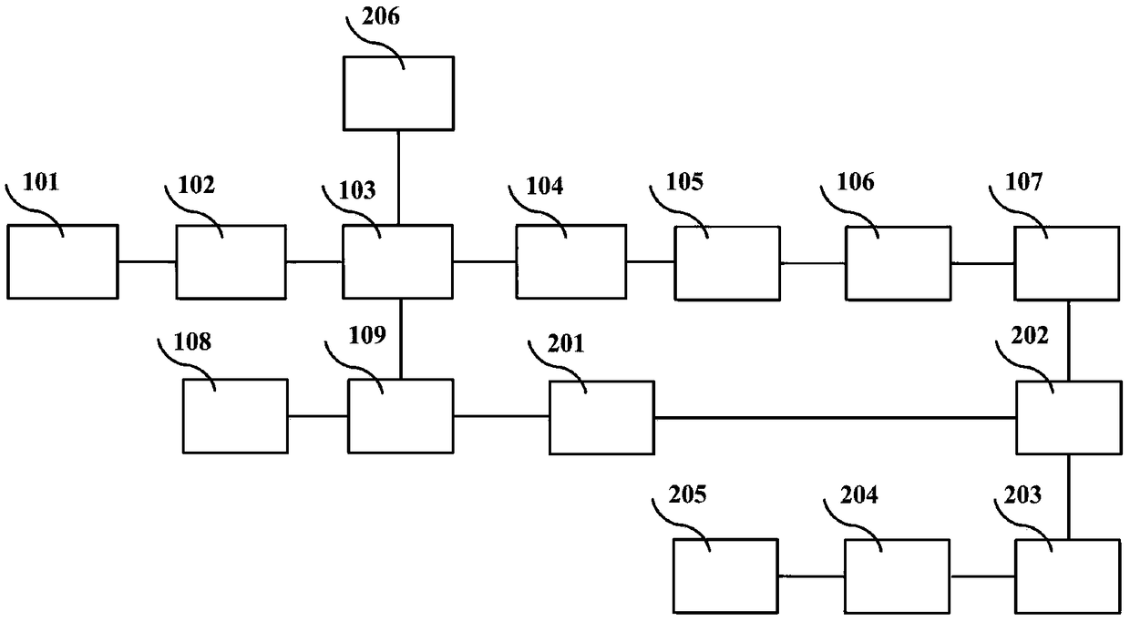
[0024] The device for measuring the mode birefringence of the high birefringence polarization-maintaining optical fiber provided in this embodiment includes a wide-spectrum light source 101, a polarizer 102 sequent...


PUM


Abstract

The invention discloses a measuring device and method of modal birefringence for high-birefringence polarization-maintaining fibers. The measuring device comprises a wide-spectrum light source, a polarizer, an electrooptical modulator, a high-birefringence polarization-maintaining fiber under measurement, a polarization analyzer, a photoelectric detector, a frequency mixer, a data acquisition circuit and a computer, as well as a frequency sweep signal source, a microwave power divider, and a microwave phase shifter. The electrooptical modulator modulates a first microwave signal to light to form a light-carried microwave signal; the light-carried microwave signal passes through the high-birefringence polarization-maintaining fiber under measurement to form two light-carried microwave signals having different optical path differences; the two light-carried microwave signals having different optical path differences pass through a photoelectric detector and are input to the radio frequency input end of the frequency mixer; the frequency mixer performs frequency mixing on the two light-carried microwave signals having different optical path differences and the second microwave signal,a medium-frequency signal passes through a low-pass filter, and a direct-current signal is input to the data acquisition circuit; the data acquisition circuit inputs frequencies at the different amplitude parts of the direct-current signal to the computer for computing. The measuring device and method herein provide precise measurement for the modal birefringence of high-birefringence polarization-maintaining fibers.

Description

technical field [0001] The invention relates to the technical field of optical fiber measurement, in particular to a device and method for measuring mode birefringence of high birefringence polarization-maintaining optical fibers. Background technique [0002] High-birefringence polarization-maintaining optical fibers are widely used in fields such as fiber optic gyroscopes, fiber optic current transformers, and polarization-maintaining optical devices. In these applications, the polarization-maintaining performance of the polarization-maintaining fiber is the key to determine its application. Generally, the mode birefringence or beat length is used to measure the polarization-maintaining performance of the polarization-maintaining fiber. Among them, the mode birefringence of the high-birefringence polarization-maintaining fiber is equal to The magnitude of the refractive index difference between the two polarization eigen axes of the polarization maintaining fiber. [0003...

Claims


Application Information

Patent Timeline
IPC IPC(8): G01M11/02
CPCG01M11/333
Inventor 孟卓朱佑强赵保来
Owner 天津博科光电科技有限公司
Learn More