Device and method for measuring multi-longitudinal mode laser resonant cavity FSR by large-amplitude laser self-mixing vibration signals

A vibration signal and laser technology, applied in the field of lasers, can solve the problems of unsuitable monitoring FSR universal measurement method, high price, low measurement accuracy, etc., achieve non-contact real-time high-precision measurement, convenient adjustment of optical path, and high measurement accuracy Effect

Active Publication Date: 2018-10-26
ANHUI UNIVERSITY
View PDF10 Cites 3 Cited by
  • Summary
  • Abstract
  • Description
  • Claims
  • Application Information

AI Technical Summary

Problems solved by technology

[0004] 1. The method of using a spectrometer to directly observe the longitudinal mode spacing, but this method is limited by the wavelength resolution of the spectrometer, and has problems such as low measurement resolution and sensitivity, low measurement accuracy, and high price;
[0005] 2. Combining the method of scanning FP and MZ interferometer and spectrum analyzer to measure FSR, but this method not only needs to combine large instruments and equipment, but also is vulnerable to the limitation of PD bandwidth, the structure of the measurement system is complex, and the cost is high
[0006] Therefore, the above-mentioned traditional method for measuring laser resonator FSR is not conducive to popularization and application, and is not suitable as a universal measurement method for monitoring FSR

Method used


Image

  • Device and method for measuring multi-longitudinal mode laser resonant cavity FSR by large-amplitude laser self-mixing vibration signals
  • Device and method for measuring multi-longitudinal mode laser resonant cavity FSR by large-amplitude laser self-mixing vibration signals
  • Device and method for measuring multi-longitudinal mode laser resonant cavity FSR by large-amplitude laser self-mixing vibration signals

Examples


Embodiment Construction

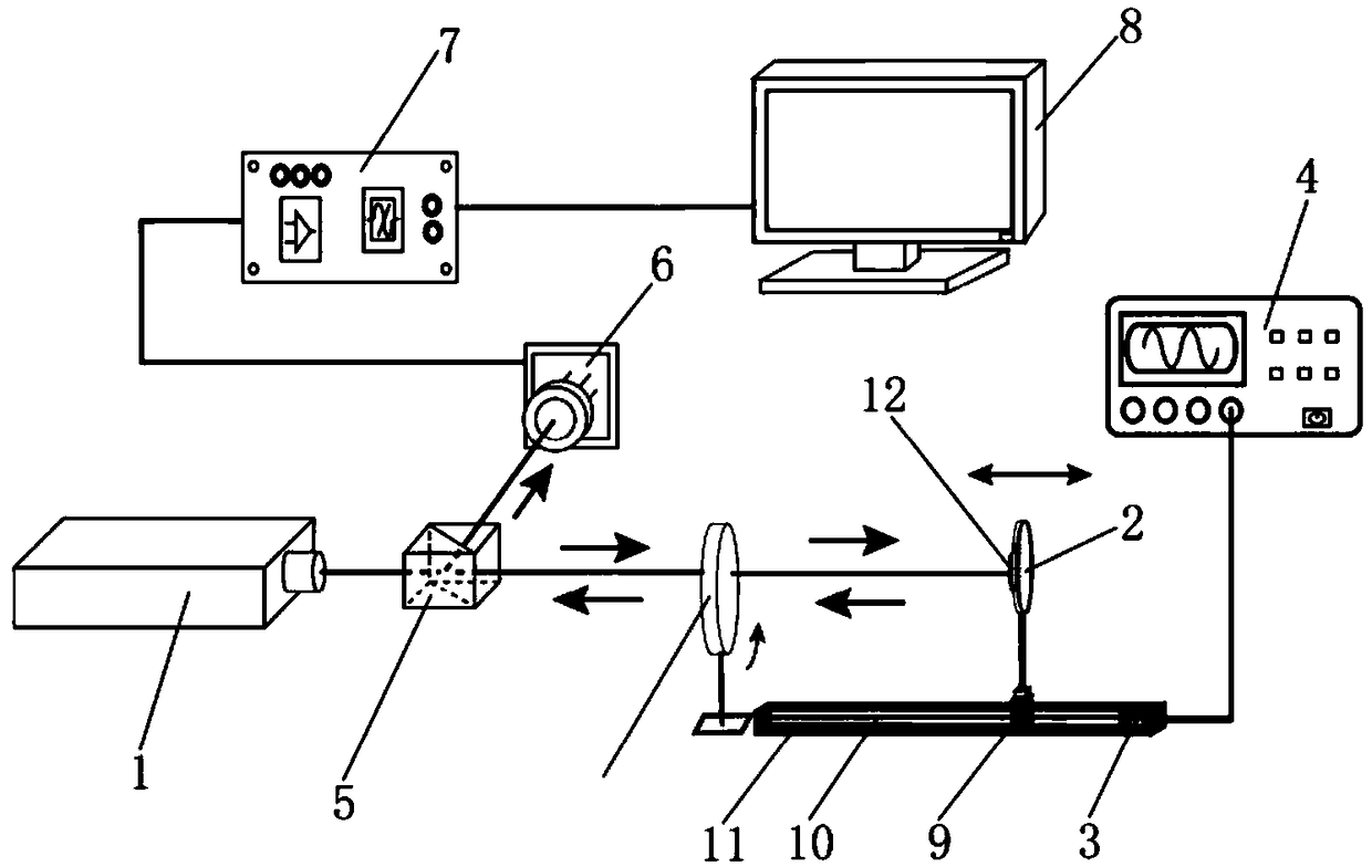
[0059] combine Figure 1 to Figure 5 , a specific embodiment of the present invention is described in detail, but the claims of the present invention are not limited in any way.

[0060] Self-mixing interferometry is a precision measurement technology, which is used for highly sensitive and precise non-contact measurement due to its simple structure, compactness and easy alignment. This technology has been widely researched and applied, mainly in the sensing and measurement of physical quantities related to object motion (such as vibration, displacement, velocity and stress, etc.) and laser-related parameters (such as: line width broadening factor α and feedback level factor C) Measurement etc.

[0061] A laser generally consists of an optical resonator, a gain medium, and an excitation source. Among them, the free spectral region of the laser resonator is defined in the same way as the free spectral region of the FP cavity etalon, and FSR is generally represented by Δν. Th...


PUM


Abstract

The invention relates to the technical field of laser devices, in particular to a device and method for measuring a multi-longitudinal mode laser resonant cavity FSR by large-amplitude laser self-mixing vibration signals. The device comprises a multi-longitudinal mode laser device, a vibrating target, a transmission mechanism, a motor, a signal generator, a beam splitter, a photoelectric detector,a signal preprocessing unit and a signal processing unit, the multi-longitudinal mode laser device emits laser to the vibrating target, by the signal generator, the motor and the transmission mechanism, the vibrating target linearly moves in a reciprocating manner, while linearly moving in a reciprocating manner, the vibrating target receives laser emitted from the multi-longitudinal mode laser device and feeds back the laser into a resonant cavity of the multi-longitudinal mode laser device to form the laser self-mixing vibration signals, the beam splitter splits the self-mixing signals to the photoelectric detector, and the output end of the photoelectric detector is successively connected with the signal preprocessing unit and the signal processing unit. Non-contact real-time high-precision measurement can be realized, the measurement device is simple in structure, measurement response speed is high, and measurement precision is also high.

Description

technical field [0001] The invention relates to the field of laser technology, in particular to a device and method for measuring the FSR of a multi-longitudinal-mode laser resonator by using a large-amplitude laser self-mixing vibration signal. Background technique [0002] Due to its inherent high brightness, high monochromaticity, high directivity and high coherence and other excellent characteristics, lasers are widely used in medical, communication, industrial and national defense and other fields. The laser resonator is the core component of the laser, and its health monitoring is an important part of maintaining the good operation of the laser. Since the indicators that affect the health of the laser resonator mainly include the free spectral region of the laser resonator (FSR for short) and the temperature of the laser resonator cavity, during the operation of the laser, the monitoring of the FSR of the laser resonator and the temperature of the laser resonator cavit...

Claims


Application Information

Patent Timeline
Patent Type & Authority Applications(China)
IPC IPC(8): G01M11/02
CPCG01M11/0207
Inventor 吕亮赵云坤俞本立毕铁柱
Owner ANHUI UNIVERSITY
Why Eureka
Try Eureka