Air pump and inflation method thereof

An inflatable pump and hydrogen technology, applied in the direction of pumps, piston pumps, pump components, etc., can solve the problems of general air tightness, reactant precipitation, and inconvenient portability, and achieve the effects of miniaturized design, convenient use, and simple structure

Inactive Publication Date: 2020-01-03
GUANGDONG UNIV OF TECH
View PDF9 Cites 0 Cited by
  • Summary
  • Abstract
  • Description
  • Claims
  • Application Information

AI Technical Summary

Problems solved by technology

However, in the actual application process, the air pump has various requirements, such as high vacuum, high efficiency, reliability, portability, etc., but most of the existing air pumps cannot meet the above requirements at the same time, such as Pumps made of various motors and mechanical structures have high inflation efficiency, but sometimes due to factors such as complex structures or long exhaust paths, the reactants precipitate and are easy to block, and the airtightness is relatively average, and some are too large due to , inconvenient to use and inconvenient to carry

Method used


Image

  • Air pump and inflation method thereof
  • Air pump and inflation method thereof

Examples


Embodiment Construction

[0031] In order to make the object, technical solution and advantages of the present invention clearer, the present invention will be further described in detail below in conjunction with the accompanying drawings. It is only stated here that the words for directions such as up, down, left, right, front, back, inside, and outside that appear or will appear in the text of the present invention are only based on the accompanying drawings of the present invention, and are not specific to the present invention. limited.

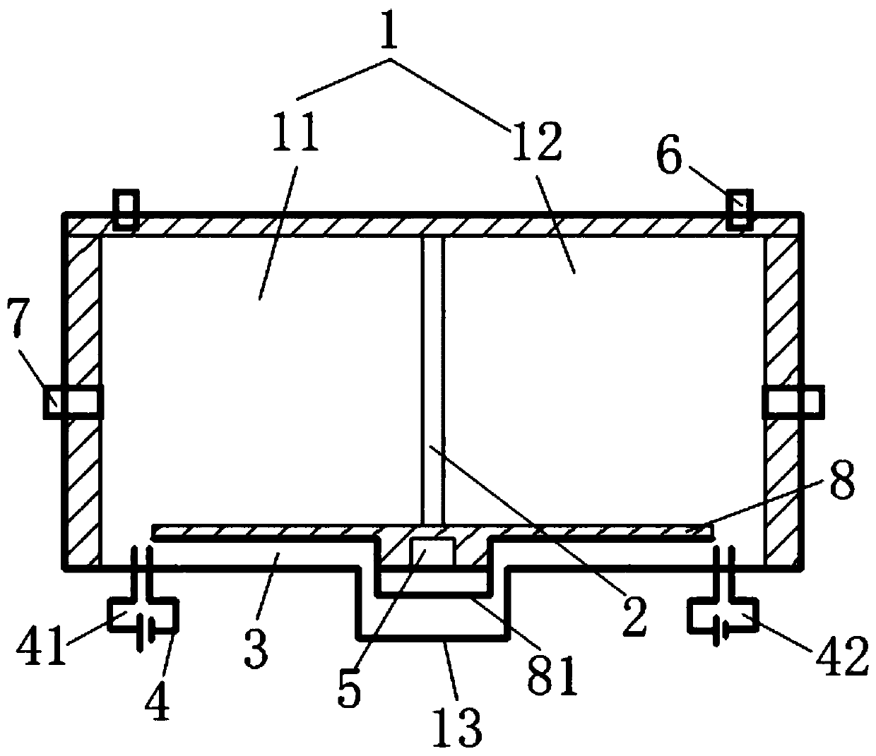
[0032] Such as figure 1 As shown, the embodiment of the present invention provides an air pump, including a cavity 1, and a piston 2 located inside the cavity 1, a water storage tank 3, an electrolysis spark circuit 4, a controller 5, and a suction check valve 6 and outlet check valve 7;

[0033] The piston 2 slides inside the cavity 1 and divides the cavity 1 into two closed reaction chambers, namely a first reaction chamber 11 and a second reaction chamber 12...


PUM


Abstract

The invention discloses an inflator pump. The inflator pump comprises a cavity, and a piston, a water storage tank, an electrolytic electric spark circuit, a controller, an air suction one-way valve and an air outlet one-way valve are located inside the cavity, wherein the piston divides the cavity into two sealed reaction cavities of a first reaction chamber and a second reaction chamber correspondingly; the electrolytic electric spark circuit is connected with the controller, and the controller is positioned inside the water storage tank, the electrolytic electric spark circuit comprises a first circuit and a second circuit, wherein the first circuit and the second circuit are located in a first reaction cavity and a second reaction cavity correspondingly; and correspondingly, the invention further provides an inflation method based on the inflator pump. According to the inflator pump, the working mode of the electrolytic electric spark circuit is controlled through the controller, the pressure of the gas inside the first reaction cavity and the pressure of the gas in the second reaction cavity are changed, so that the gas suction process and inflation process of the inflator pump are realized, the structure is simple, the carrying is convenient, and the use is convenient.

Description

technical field [0001] The invention relates to the technical field of inflation equipment, in particular to an air pump and an inflation method thereof. Background technique [0002] With the development of vacuum technology and portable inflatable devices, there are many types of air pumps, ranging from various mechanical motor vacuum pumps to different types of micropumps. However, in the actual application process, the air pump has various requirements, such as high vacuum, high efficiency, reliability, portability, etc., but most of the existing air pumps cannot meet the above requirements at the same time, such as Pumps made of various motors and mechanical structures have high inflation efficiency, but sometimes due to factors such as complex structures or long exhaust paths, the reactants precipitate and are easy to block, and the airtightness is relatively average, and some are too large , inconvenient to use and inconvenient to carry. Based on this, it is necessa...

Claims


Application Information

Patent Timeline
Patent Type & Authority Patents(China)
IPC IPC(8): F04B35/00F04B39/10C25B1/04
CPCC25B1/04F04B35/00F04B39/10Y02E60/36
Inventor 陈裕爵孙敏洁陈桪吴国庆魏远洋陈章俊张倍嘉骆志明庞方丹何超
Owner GUANGDONG UNIV OF TECH
Why Eureka
Try Eureka