Limiting device and limiting device control system

A technology of limit device and central control system, which is applied in the direction of outboard propulsion device, propulsion device engine, transportation and packaging, etc. It can solve the problems of ship's travel resistance, easy damage of rotating shaft and limit device, and large limit torque. Achieve the effect of not occupying the working space, simple structure and reliable limit

Inactive Publication Date: 2018-10-26
SHANGHAI MERCHANT SHIP DESIGN & RES INST
View PDF5 Cites 0 Cited by
  • Summary
  • Abstract
  • Description
  • Claims
  • Application Information

AI Technical Summary

Problems solved by technology

[0005] If the fixed structure in the prior art is used as the limit device to limit the underwater device, the above problems also exist, and the fixed structure protrudes in the water and cannot be stored, and the area connected to the inside and outside of the underwater mechanism has produced Certain obstacles, for example, will block the flow of fluid in its transverse pipes, causing greater travel resistance to ships, etc.
[0006] In order to avoid the above problems, at present, for the outboard turning mechanism, most of the limiting devices used are to limit the rotating shaft of the turning mechanism. However, such a structure will generate a lot of stress, so that the force condition of the limiting device Not ideal, the limit will generate a large torque due to too small torque, the shaft and the limit device are easily damaged

Method used


Image

  • Limiting device and limiting device control system
  • Limiting device and limiting device control system
  • Limiting device and limiting device control system

Examples


Embodiment Construction

[0059] The technical solutions of the present invention will be clearly and completely described below in conjunction with the accompanying drawings. Apparently, the described embodiments are some of the embodiments of the present invention, but not all of them. Based on the embodiments of the present invention, all other embodiments obtained by persons of ordinary skill in the art without making creative efforts belong to the protection scope of the present invention.

[0060] In the description of the present invention, it should be noted that the orientation or positional relationship indicated by the terms "center", "upper", "lower", "vertical", "horizontal", "inner" and "outer" are based on The orientation or positional relationship shown in the drawings is only for the convenience of describing the present invention and simplifying the description, and does not indicate or imply that the referred device or element must have a specific orientation, be constructed and opera...


PUM


Abstract

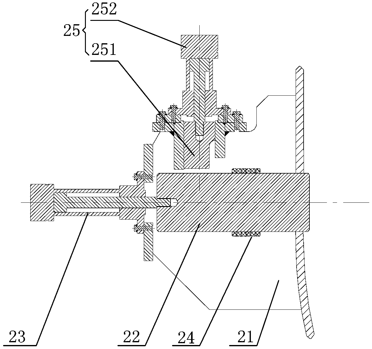
The invention relates to a limiting device and a limiting device control system. The limiting device is provided with a mounting base, a movable pin and a movable pin driving assembly; a through holeis formed in the mounting base; the movable pin is inserted in the through hole; and the movable pin driving assembly is mounted on the mounting base and used for controlling the movable pin to stretch out of or draw back into the through hole. The limiting device control system comprises a central control system, a sensor and the limiting device; the sensor and the movable pin driving assembly are connected with the central control system; the sensor is used for collecting working state information of a limited mechanism and transmitting the collected information to the central control system; and the central control system is used for controlling the working state of the movable pin driving assembly according to the information collected by the sensor, and then controlling the movable pin to stretch out of or draw back into the through hole. The limiting device is reliable in limiting and simple in structure, and equipment operation is not affected; and the limiting device control system can remotely control the limiting device and is convenient to use.

Description

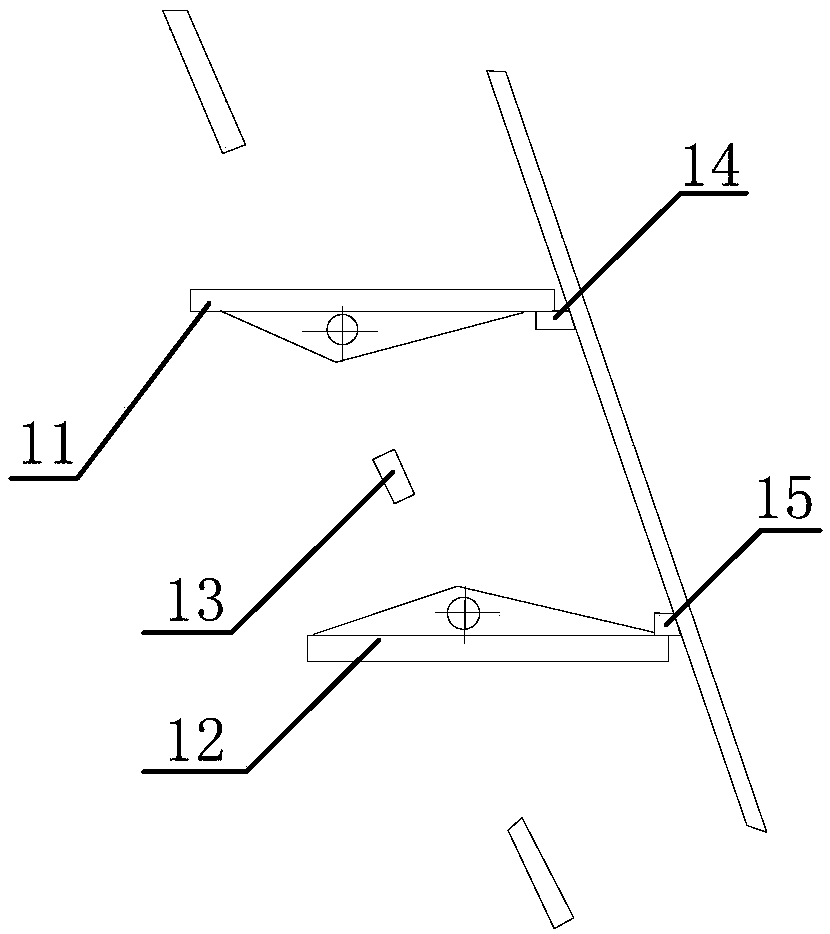
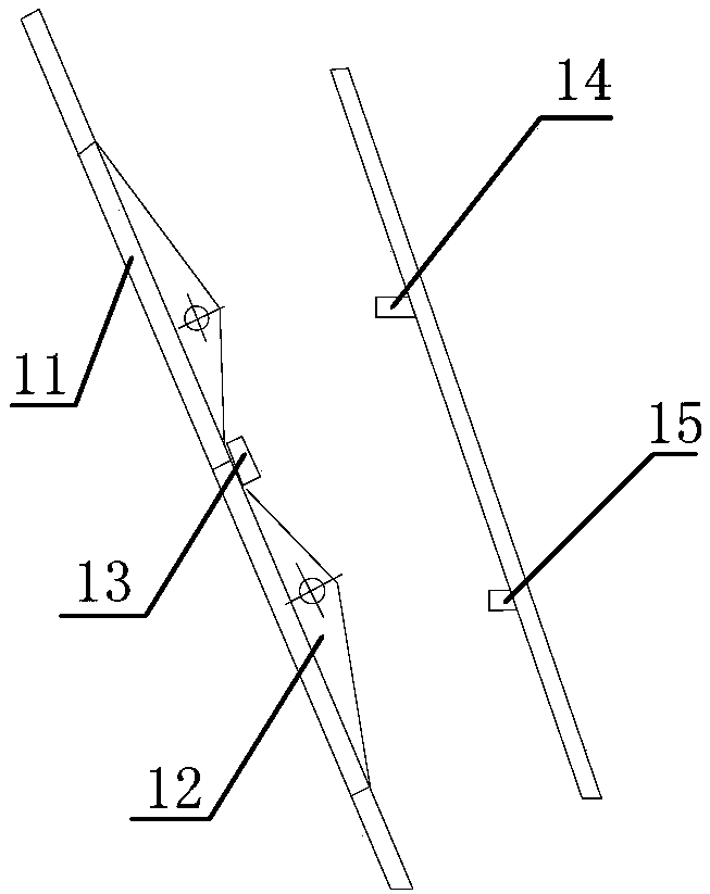
technical field [0001] The invention relates to a limit device and a control system of the limit device. Background technique [0002] In the prior art, a fixed structure is often used to limit the position of the limited mechanism. Since the limiting part is fixed and cannot be changed, it is often only possible to limit the limited mechanism in one direction. [0003] For example, Figure 1A and Figure 1B It is a schematic diagram of working conditions with a fixed structure as a limit device, wherein, Figure 1A It shows the schematic diagram of the first working condition with the fixed structure as the limit device, Figure 1B A schematic diagram showing the second working condition with a fixed structure as a limit device. As shown in the figure, the first limited mechanism 11 and the second limited mechanism 12 perform open or close movements respectively, wherein the first working condition is the open state, and the second working condition is the closed state. ...

Claims


Application Information

Patent Timeline
Patent Type & Authority Applications(China)
IPC IPC(8): B63H20/10
CPCB63H20/10
Inventor 刘向冬黎峰顾剑刚
Owner SHANGHAI MERCHANT SHIP DESIGN & RES INST
Why Eureka
Try Eureka