
Engineering vehicle lifting equipment

A technology of engineering vehicles and lifting equipment, which is applied to the arrangement of loading and unloading vehicles, vehicles with cranes, vehicles used for freight, etc., and can solve the problems that engineering vehicles do not have lifting functions, lifting equipment does not have transportation functions, and the cost of lifting equipment is high. , to achieve practicality, save manpower and improve work efficiency

Inactive Publication Date: 2018-10-26
周伟冬
View PDF0 Cites 4 Cited by
  • Summary
  • Abstract
  • Description
  • Claims
  • Application Information

AI Technical Summary

Problems solved by technology

[0002] The transportation volume of engineering vehicles is relatively large, and other lifting equipment is generally required for loading goods. However, the cost of using lifting equipment is relatively high, resulting in high cost and low profit. The current lifting equipment does not have the function of transportation, and Engineering vehicles with transportation functions do not have lifting functions, and a combination of the two is required to complete the lifting and transportation work. At present, there is no transportation engineering vehicle with lifting equipment to solve the above problems

Method used


Image

  • Engineering vehicle lifting equipment
  • Engineering vehicle lifting equipment
  • Engineering vehicle lifting equipment

Examples


Embodiment Construction

[0025] The following will clearly and completely describe the technical solutions in the embodiments of the present invention with reference to the accompanying drawings in the embodiments of the present invention. Obviously, the described embodiments are only some, not all, embodiments of the present invention. Based on the embodiments of the present invention, all other embodiments obtained by persons of ordinary skill in the art without making creative efforts belong to the protection scope of the present invention.

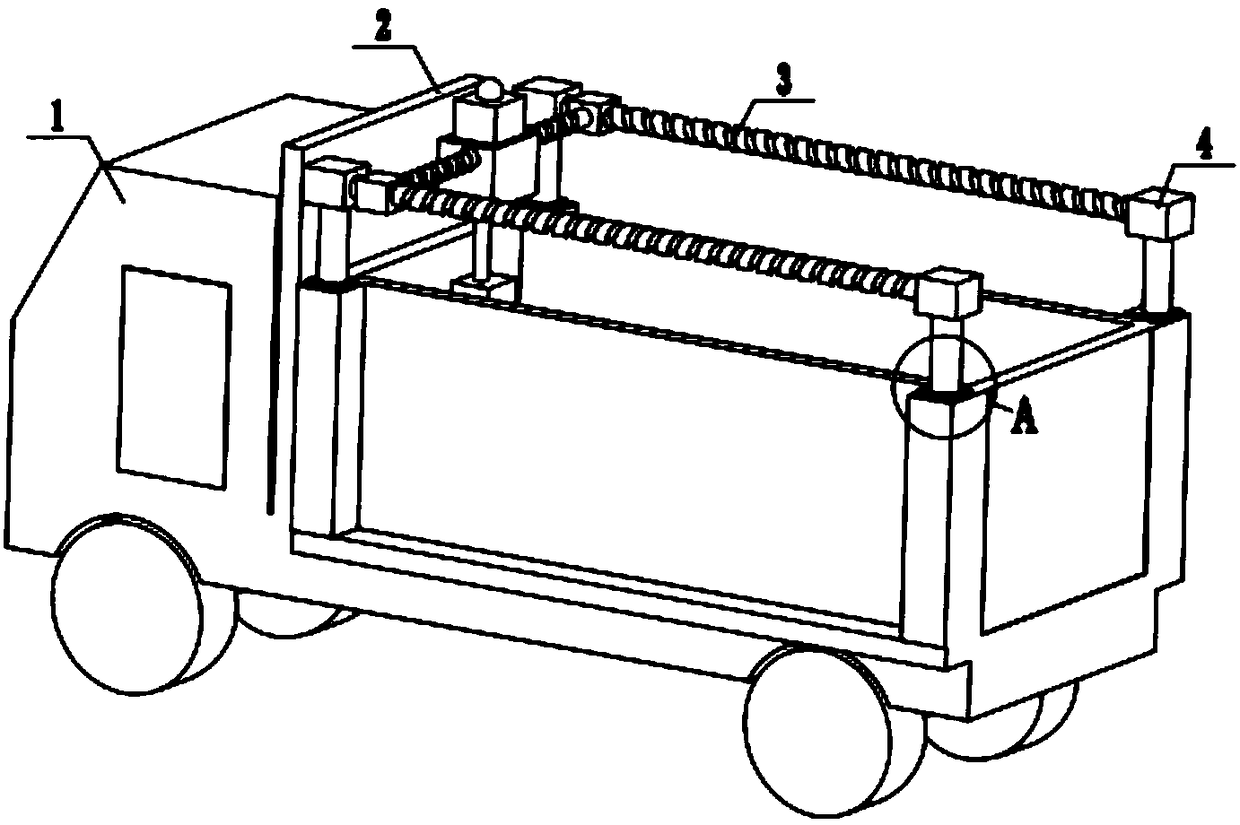
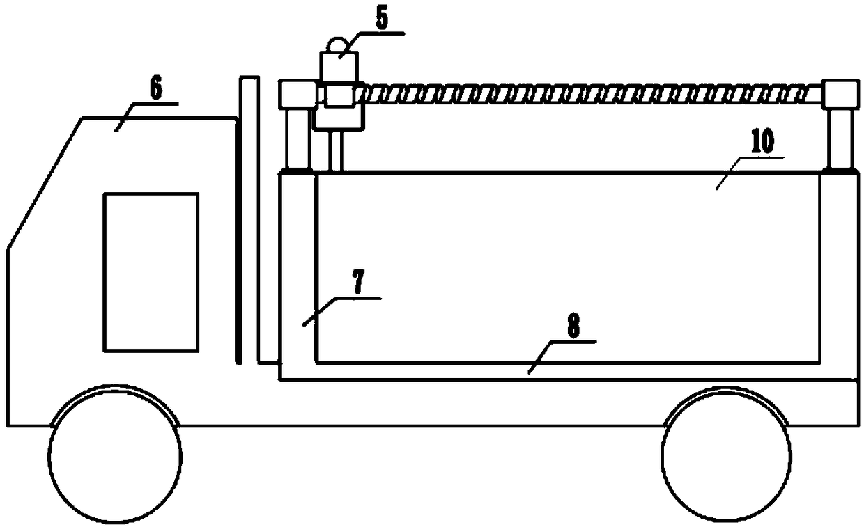
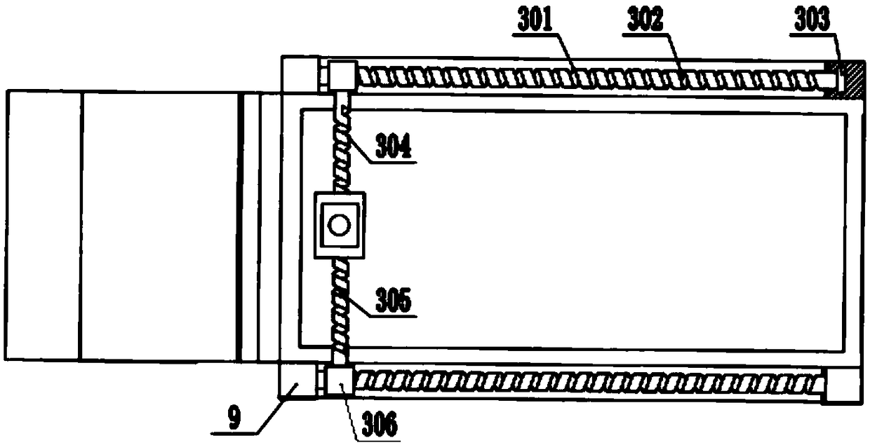
[0026] see Figure 1-5 As shown, a kind of engineering vehicle lifting equipment of the present embodiment includes an engineering vehicle 1, a transmission shaft 3, a lifting device 5, and a lifting cylinder 7. The engineering vehicle 1 includes a compartment 10, a driver's cab 6, and the lifting cylinder 7 The number is four, and the lifting cylinder 7 includes a piston rod 702 and a cylinder barrel 703. The four cylinder barrels are respectively arranged on...


PUM


Abstract

The invention discloses engineering vehicle lifting equipment. The engineering vehicle lifting equipment comprises an engineering vehicle, transmission shafts, a lifting device and lifting cylinders.The engineering vehicle comprises a compartment and a cab. The lifting cylinders comprises piston rods and four cylinder barrels, and the four cylinder barrels are separately arranged on two sides ofthe front end and the rear end of the compartment and are fixedly connected with the compartment. The piston rods are disposed in cushion blocks and are slidably connected to the cylinder barrels, andsupporting blocks are arranged at the upper ends of the two piston rods disposed on the rear side of the compartment. The transmission shafts include conveying shafts and a fixing shaft, and the supporting blocks and conveying motors which are disposed on the same side are connected through the conveying shafts. The lifting device comprises an adjusting motor, a rope box, a rope and a hook, and sliding holes are formed in the rope box. The sliding holes are matched with the fixing shaft, and the adjusting motor is disposed at the upper end of the rope box. One end of the rope is disposed in the rope box, and the other end of the rope is disposed outside the lower end of the rope box. The cab is internally provided with a control device which is electrically connected with the adjusting motor, the lifting cylinders and the conveying motors.

Description

technical field [0001] The invention relates to the field of lifting equipment, in particular to an engineering vehicle lifting equipment. Background technique [0002] The transportation volume of engineering vehicles is relatively large, and other lifting equipment is generally required for loading goods. However, the cost of using lifting equipment is relatively high, resulting in high cost and low profit. The current lifting equipment does not have transportation functions, and Engineering vehicles with transportation functions do not have lifting functions, and a combination of the two is needed to complete the lifting and transportation work. At present, there is no such thing as a transportation engineering vehicle with lifting equipment to solve the above problems. Contents of the invention [0003] The object of the present invention is to provide a lifting device for engineering vehicles to solve the problems raised in the background technology above. [0004] T...

Claims


Application Information

Patent Timeline
IPC IPC(8): B60P1/54
CPCB60P1/5457
Inventor 周伟冬
Owner 周伟冬
Learn More