Magnet drive electric shaver
A technology of electric shaver and drive unit, which is applied in metal processing and other directions, can solve problems such as the failure of the drive shaft and transmission shaft, large vibration and noise of the machine, and machine jamming, so as to avoid vibration transmission, reduce vibration and Pulling feeling, breakage prevention effect
- Summary
- Abstract
- Description
- Claims
- Application Information
AI Technical Summary
Problems solved by technology
Method used
Image
Examples
Embodiment 1
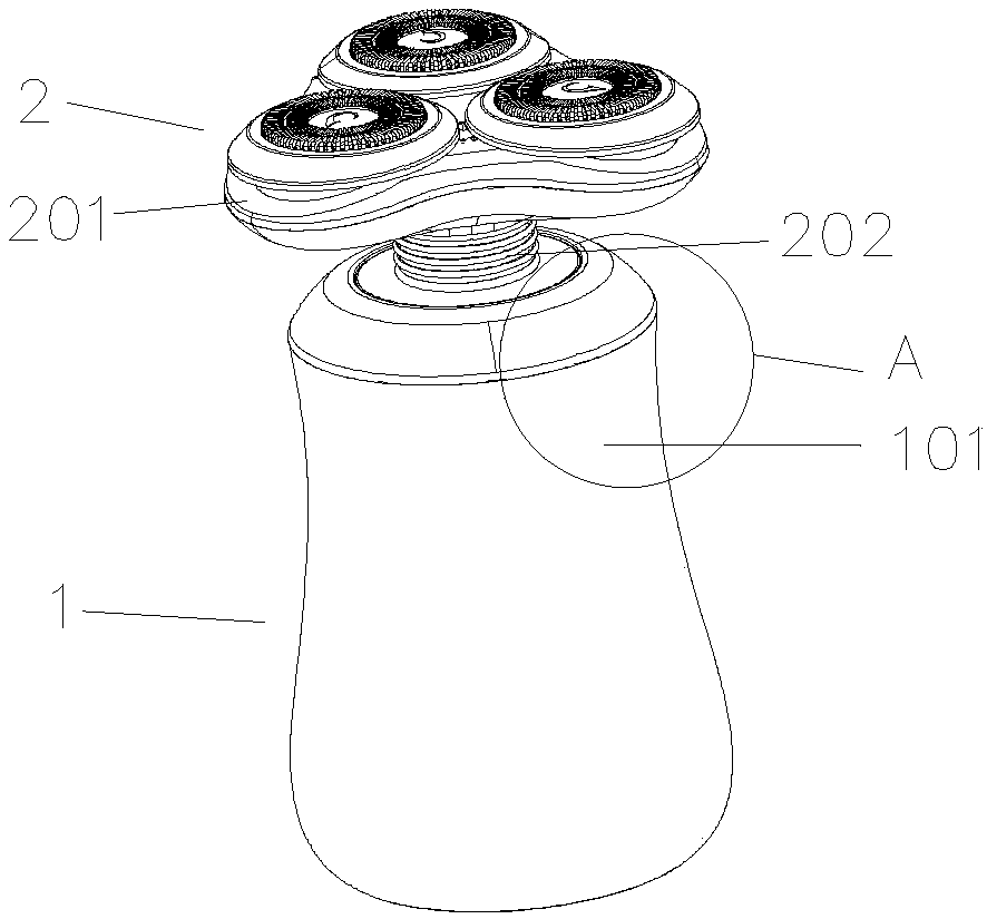
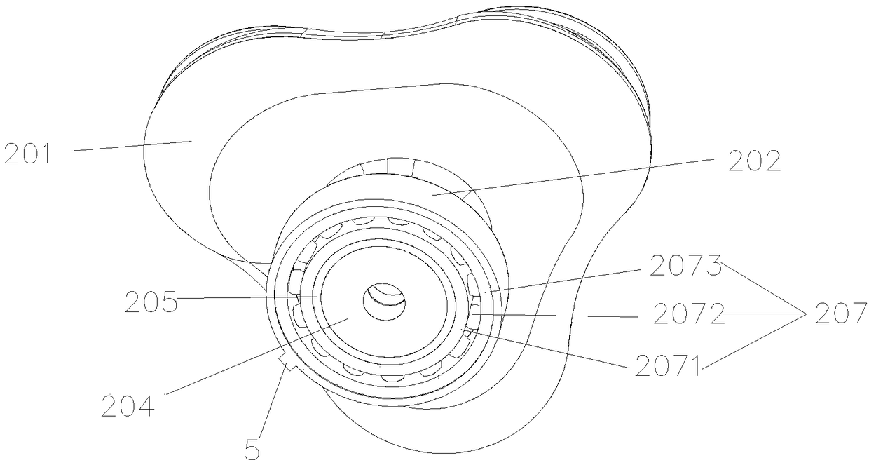
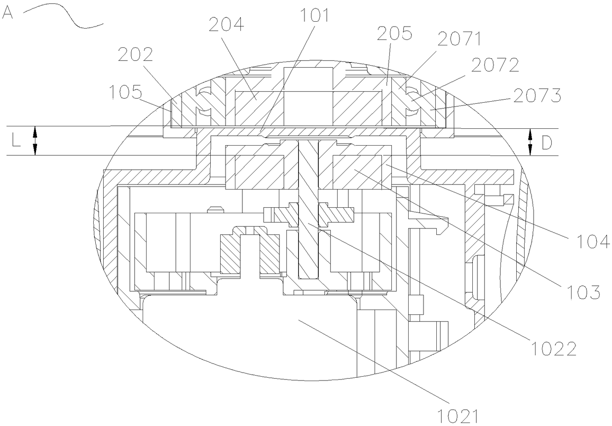
[0036] like Figures 1 to 3 As shown, a magnetically driven electric shaver includes a main body assembly 1 and a cutter head assembly 2, and the cutter head assembly 2 is arranged on the main body assembly 1. Unit 102, a battery that provides power for the drive unit 102, the battery is located in the body 101, a USB charging port for charging the battery, the cutter head assembly 2 includes a moving knife unit 203 and a shell for supporting the moving knife unit 203 Body 201, a knife net arranged outside the moving knife unit 203, the knife net is used to cooperate with the moving knife unit 203 to shave beards, the drive unit 102 includes a motor 1021, wherein the drive unit 102 also includes a The active magnet 103 inside and the driven magnet 204 arranged in the housing 201 , the movable knife unit 203 is driven to rotate under the action of the motor 1021 , the active magnet 103 and the driven magnet 204 . There is a transmission module between the driven magnet 204 and...
Embodiment 2
[0056] The difference between embodiment one and embodiment two is that, as Figure 7 , Figure 8 As shown, the upper end of the body 101 is provided with a second boss, and the second boss at least partially extends into the connecting neck 202. The advantage is that the reliability of the transmission is ensured, so that the head assembly 2 of the shaver is in operation. Do not shift.
[0057] The connection between the second boss and the connecting neck 202 is through an anti-rotation structure, which prevents the cutter head assembly 2 from shifting during the working process and makes the transmission invalid. The anti-rotation structure may be a turn-lock fit between the second boss and the connecting neck 202; or, the outer wall of the second boss is provided with a first groove, and the inner wall of the connecting neck 202 is provided with a first groove. The groove fits the first protrusion, and the first protrusion extends toward the center line of the cutter hea...
PUM
 Abstract
Description
Claims
Application Information
 - R&D
- Intellectual Property
- Life Sciences
- Materials
- Tech Scout
- Unparalleled Data Quality
- Higher Quality Content
- 60% Fewer Hallucinations
Browse by: Latest US Patents, China's latest patents, Technical Efficacy Thesaurus, Application Domain, Technology Topic, Popular Technical Reports.
© 2025 PatSnap. All rights reserved.Legal|Privacy policy|Modern Slavery Act Transparency Statement|Sitemap|About US| Contact US: help@patsnap.com


