Eureka AIR delivers breakthrough ideas for toughest innovation challenges, trusted by R&D personnel around the world.

Electrical automatic paint spraying device

An electrical automation, paint spray head technology, applied in spray devices, spray booths, manipulators, etc., can solve problems such as being unsuitable for long-term development and use, uneven paint on the surface of objects, low equipment work efficiency, etc., to reduce paint drying. time, reasonable and novel design, and the effect of improving paint uniformity

Inactive Publication Date: 2018-10-23
赵瑞霞
View PDF11 Cites 6 Cited by
  • Summary
  • Abstract
  • Description
  • Claims
  • Application Information

AI Technical Summary

Problems solved by technology

[0003] However, the existing paint spraying devices generally use compressed air to atomize the paint air, which wastes the paint, and causes uneven paint on the surface of the object, and the paint spray paint takes a certain time to dry, resulting in low efficiency of the equipment, especially for winter and cold In terms of areas, the paint is easy to thicken or freeze, which seriously affects the efficiency of painting, and is easy to cause equipment damage, so it is not suitable for long-term development and use

Method used


Image

  • Electrical automatic paint spraying device
  • Electrical automatic paint spraying device
  • Electrical automatic paint spraying device

Examples


Embodiment Construction

[0020] In order to make the technical means, creative features, goals and effects achieved by the present invention easy to understand, the present invention will be further described below in conjunction with specific embodiments.

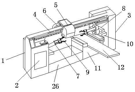
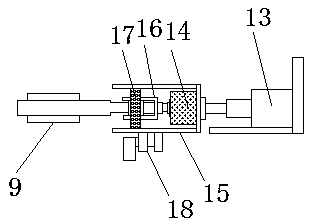
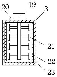
[0021] like Figure 1-4 As shown, an electrical automatic painting device includes a frame 1, a power distribution cabinet 2, a paint supply cylinder 3 and a slide rail 4, the power distribution cabinet 2 is fixedly connected to one end of the frame 1, and the paint supply cylinder 3 is fixed Connected to the other end of the frame 1, the slide rail 4 is fixedly connected to the top of the frame 1, one side of the slide rail 4 is slidably connected to a paint spraying head 5, and one side of the paint spraying head 5 is fixedly connected to a feed pipe 6, The side wall of the power distribution cabinet 2 is fixedly connected to a No. 1 mechanical arm 7, and the side wall of the paint supply tube 3 is fixedly connected to a No. 2 mechanical arm 8. ...


PUM


Abstract

The invention discloses an electrical automatic paint spraying device. The electrical automatic paint spraying device comprises a rack, a power distribution cabinet, a paint supplying barrel and a sliding rail. The power distribution cabinet is fixedly connected to one end of the rack. The paint supplying barrel is fixedly connected to the other end of the rack. The sliding rail is fixedly connected to the top of the rack. One side of the sliding rail is slidably connected with a paint spraying head. One side of the paint spraying head is fixedly connected with a feeding pipe. One side wall ofthe power distribution cabinet is fixedly connected with a first mechanical arm. One side wall of the paint supplying barrel is fixedly connected with a second mechanical arm. One ends of the first mechanical arm and the second mechanical arm are fixedly connected with mechanical grippers correspondingly. The bottom of the second mechanical arm is fixedly connected with an air blowing table. Theelectrical automatic paint spraying device is reasonable and novel in design and convenient to operate and use, paint materials can be stirred and heated, paint spraying uniformity on the surface of the spraying paint raw materials is effectively improved, meanwhile the spraying paint raw materials of different diameters can be treated, the product paint spraying efficiency can be effectively improved, and the electrical automatic paint spraying device has high practicality and is suitable for widespread use and promotion.

Description

technical field [0001] The invention relates to the field of electrical automation, in particular to an electrical automation painting device. Background technique [0002] Paint (paint or coating) is a chemical mixture coating that can firmly cover the surface of an object for protection, decoration, marking and other special purposes. As a kind of coating, paint can be coated on the surface of objects by different construction techniques to form a solid film with strong adhesion, certain strength and continuity; the film formed in this way is commonly called coating film, also known as paint film or coating. Coatings are generally composed of film-forming substances, fillers (pigments and fillers), solvents, and additives. They belong to organic chemical polymer materials, and the formed coating film belongs to the type of polymer compounds; according to the classification of modern chemical products, coatings Belongs to fine chemical products; modern coatings are gradual...

Claims


Application Information

Patent Timeline
IPC IPC(8): B05B16/20B05B13/04B05B15/25B05B15/00B05B14/00B05B13/02B25J9/12
CPCB05B13/0221B05B13/041B05B14/00B05B15/00B05B15/25B05B16/20B25J9/123
Inventor 赵浩
Owner 赵瑞霞
Why Eureka
Eureka Blog
Learn More