
A nanobubble generator

A nano-bubble and generator technology, used in solid separation, flotation and other directions, can solve the problems of large size of foam and inability to fully recover fine-grained minerals, achieve large bubble volume, stable size, and improve flotation efficiency. Effect

Inactive Publication Date: 2020-01-10
SOUTHWEAT UNIV OF SCI & TECH
View PDF7 Cites 0 Cited by
  • Summary
  • Abstract
  • Description
  • Claims
  • Application Information

AI Technical Summary

Problems solved by technology

[0004] In view of this, the purpose of the present invention is to provide a nano-bubble generator to solve the problem that the foam particle size produced by the existing foam emitter is large and cannot fully recover the fine-grained minerals

Method used


Image

  • A nanobubble generator
  • A nanobubble generator

Examples


Embodiment Construction

[0022] The present invention will be further described below in conjunction with the accompanying drawings and embodiments.

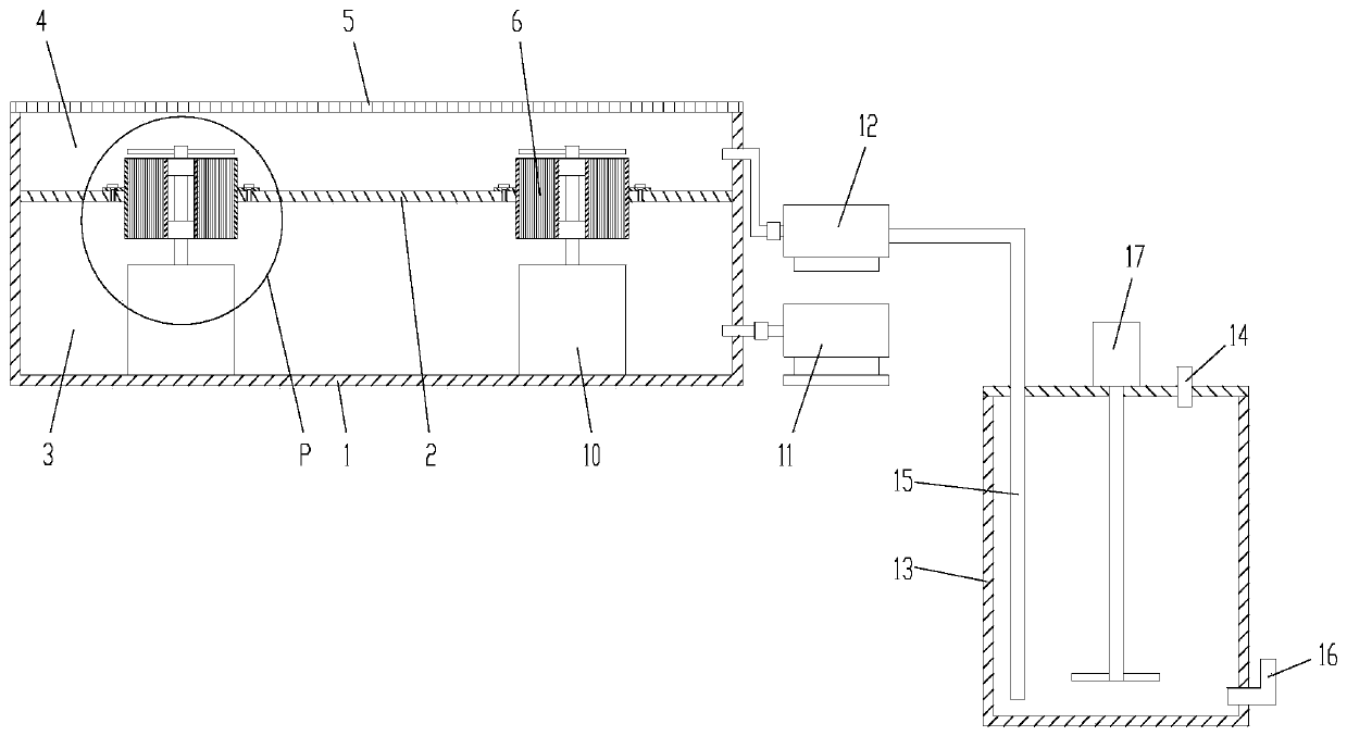
[0023] As shown in the figure, the nanobubble generator of this embodiment includes a casing 1 with an upper opening, and a horizontal partition 2 is arranged in the middle of the casing, and the horizontal partition divides the casing into upper and lower parts. The lower part is an air chamber 3, and the upper part is a gas-liquid mixing chamber 4. The upper end of the housing is also provided with a filter plate 5, which is used to prevent particles from falling into the gas-liquid mixing chamber.

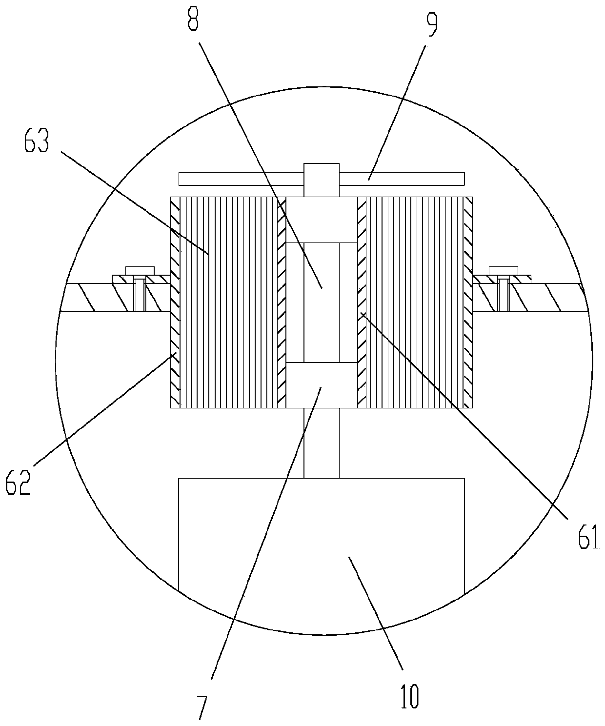
[0024] The nanobubble generator also includes several micro-flow tubes 6 evenly arranged on the horizontal partition, and the micro-flow tubes include an inner tube 61, an outer tube 62, and a copper foil arranged between the inner tube and the outer tube Roll 63, the copper foil roll is made of copper foil etched with micro-airflow channels on the surfac...


PUM


Abstract

The invention discloses a nano bubble generator. The nano bubble generator comprises a shell, a horizontal partition plate, a filter plate and microflow tubes; the microflow tubes comprise an inner tube, an outer tube and a copper foil roll arranged between the inner tube and the outer tube, and the copper foil roll is prepared from a copper foil of which the surface is provided with micro air flow groove channels in an etching mode; and the nano bubble generator further comprises an air pump used for injecting air into an air cavity and a water pump used for injecting water into an air-liquidmixing cavity. According to the nano bubble generator, the copper foil which is provided with a large quantity of micro air flow groove channels in the etching mode is rolled to form the microflow tubes, high-pressure air generates a large quantity of micro air flows through the microflow tubes, the micro air flows are sheared by a blade rotating at high speed, and then a large quantity of nano bubbles are formed in the air-liquid mixing cavity. According to the nano bubble generator, the size of the nano bubbles generated by the nano bubble generator can be controlled by controlling the diameter of the micro air flow groove channels and the rotation speed of a motor, the generated nano bubbles are stable in size and large in bubble quantity, the flotation efficiency can be improved, andthe mineral recovery rate can be increased.

Description

technical field [0001] The invention relates to the technical field of mineral flotation, in particular to a device for flotation using nano-bubbles. Background technique [0002] Foam flotation is often used to separate fine minerals. Compared with shaking table mineral separation, high gradient magnetic separation and oil accumulation, bubble flotation has better efficiency and lower cost. The main principle of the flotation method is based on the difference in the chemical properties of the surface of minerals and slag, using the natural hydrophobicity of the surface of mineral particles and the hydrophilicity of slag to separate minerals and impurities. [0003] With the continuous development and consumption of mineral resources on the earth by human beings, rich ore and easy-to-handle ore resources are decreasing day by day, while the demand for metal materials is increasing, so poor, fine and miscellaneous ores have to be mined and sorted. This type of ore must be gr...

Claims


Application Information

Patent Timeline
Patent Type & Authority Patents(China)
IPC IPC(8): B03D1/02
CPCB03D1/025
Inventor 彭铁锋
Owner SOUTHWEAT UNIV OF SCI & TECH
Learn More