
Air Pre-filter and Air Filtration System for Engine

An air pre-filter and engine technology, applied in the direction of fuel air filter, combustion air/combustion-air treatment, engine components, etc., can solve the problems of slow rotation of first-stage blades, large volume of air filter, and difficult to meet the space requirements, etc.

Active Publication Date: 2018-10-19
WEICHAI POWER CO LTD
View PDF5 Cites 5 Cited by
  • Summary
  • Abstract
  • Description
  • Claims
  • Application Information

AI Technical Summary

Problems solved by technology

The first-stage blade pre-filter can only sweep out larger particles of dust, and the second-stage swirl tube-type coarse filter, the swirl blades cannot rotate and only have a guiding function, and the dust is thrown out only by the centrifugal force of the air passing through the rotating blades. Low cleaning efficiency
In order to ensure the centrifugal force when the air passes through the swirl blades, the outer diameter of the swirl tube is designed to be small, and the multi-swirl tube arrangement is adopted, resulting in large air intake resistance and poor air intake, resulting in slow rotation of the primary blade and slow rotation of the secondary swirl. Small centrifugal force, therefore, low filtration efficiency
At the same time, the exhaust gas of the engine is used for dust removal, and the filtration efficiency is low due to the unstable pressure of the exhaust gas.
In addition, due to the low filtration efficiency of the existing pre-filter mechanism, the main body of the air filter needs to ensure the filtration efficiency, which increases the size of the paper filter element, which in turn leads to a generally large volume of the air filter
In the high-emission stage, construction machinery and agricultural machinery need to arrange various post-processing devices in the engine compartment. If large-volume air filters continue to be arranged, the space is difficult to meet the requirements

Method used


Image

  • Air Pre-filter and Air Filtration System for Engine
  • Air Pre-filter and Air Filtration System for Engine
  • Air Pre-filter and Air Filtration System for Engine

Examples


Embodiment Construction

[0030] Exemplary embodiments of the present disclosure will be described in more detail below with reference to the accompanying drawings. Although exemplary embodiments of the present disclosure are shown in the drawings, it should be understood that the present disclosure may be embodied in various forms and should not be limited by the embodiments set forth herein. Rather, these embodiments are provided for more thorough understanding of the present disclosure and to fully convey the scope of the present disclosure to those skilled in the art.

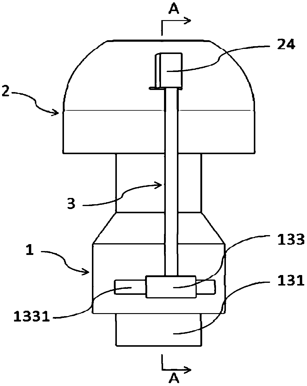
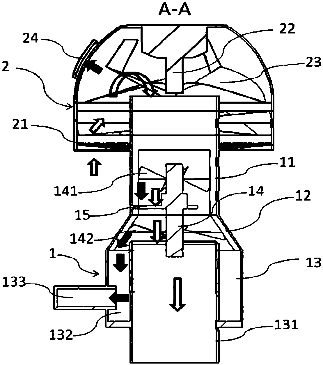
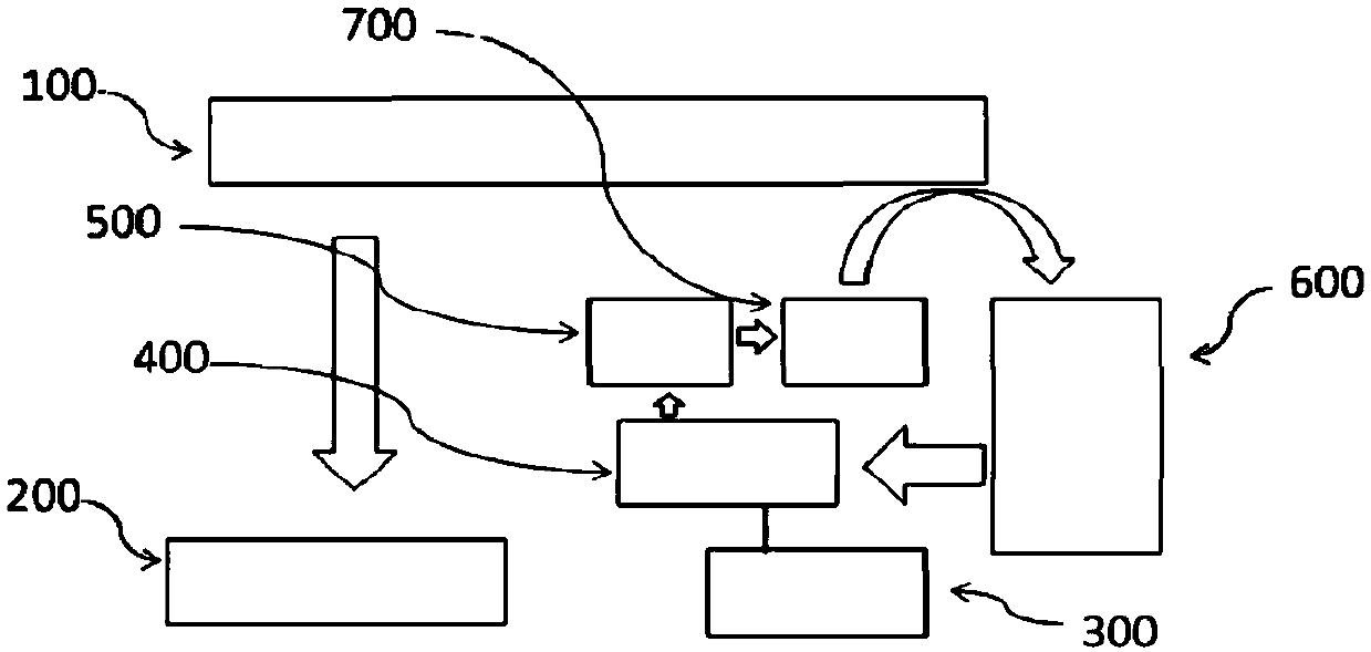
[0031]Please refer to figure 1 and figure 2 , in a specific embodiment, the air pre-filter provided by the present invention includes a pre-filter pipe 1, and the air inlet of the pre-filter pipe 1 is coaxially provided with a pre-filter cover 2 with a dust outlet, so The air inlet of the pre-filter pipe 1 is affixed to the inside of the opening end of the pre-filter cover 2 through the guide vane group 21. The first rotating bla...


PUM


Abstract

The present invention discloses an air pre-filter and an air filtration system for use in an engine, which includes a pre-filter tube. A pre-filter cage, which has a dust outlet, is provided at a gasinlet of the pre-filter tube. A first rotating blade is placed in the pre-filter cage, while a second rotating blade and a third rotating blade are provided inside the pre-filter tube with spacing therebetween. An installing tube is provided at a gas outlet of the pre-filter tube, and a dust storage chamber is formed between the outer wall of the installing tube and the inner wall of the pre-filter tube. The dust storage chamber is connected with a dust exhausting cell, which has a dust exhausting passage, through a dust exhausting hole. The dust exhausting cell interconnects with the dust outlet through pipe connection, and the dust exhausting passage interconnects with a pressure stabilizing gas source through plumbing. The air filtration system which has the above air pre-filter also includes a compressed gas tank, a pressure regulator and an air filter. The compressed gas tank is connected with an air compressor; the air filter is connected with the installing tube; and the compressed gas tank and the pressure regulator is connected with the dust exhausting passage. Intake air is pre-filtered by multistage rotating blades and no cyclone structure is present in the pre-filteringtube, which reduces the resistance of the intake air and improves the efficiency of filtrating. The pressure stabilizing gas source makes the process of dust exhausting controllable, which improves the efficiency of dust exhausting.

Description

technical field [0001] The invention relates to the technical field of auto parts manufacturing, in particular to an air pre-filter for an engine, and also relates to an air filter system comprising the above-mentioned air pre-filter. Background technique [0002] The engine is the heart of the internal combustion engine, and the air filter is the lungs of the engine. The air inhaled during the working process of the engine directly affects the performance of the engine function, work stability, reliability, environmental protection, and even greatly affects the life of the engine. Statistics show that most of the failures of the engine, such as early wear, heavy smoke, high fuel consumption, and powerlessness, are related to the quality of intake air, accounting for more than 85%. Generally, the better the intake air quality of internal combustion machinery and the smaller the intake resistance, the better the performance of the entire intake system and the better the engi...

Claims


Application Information

Patent Timeline
IPC IPC(8): F02M35/08F02M35/022
CPCF02M35/0223F02M35/084
Inventor 贾帅帅隋鹏超胡洪昌杨涛曹东明刘相杰
Owner WEICHAI POWER CO LTD
Learn More