Automatic thermal cutting apparatus for riser of abrasion- resistant sleeve casting

A wear-resistant sleeve, thermal cutting technology, used in auxiliary devices, welding/cutting auxiliary equipment, gas flame welding equipment, etc. Guaranteed service life and the effect of reducing resistance

Inactive Publication Date: 2018-10-19
JIANGSU XINGYUAN POWER PLANT & METALLURGICAL EQUIP MFG
View PDF0 Cites 3 Cited by
  • Summary
  • Abstract
  • Description
  • Claims
  • Application Information

AI Technical Summary

Problems solved by technology

Among them, the latter, as a common application method with simple operation and low cost, is widely used in the actual production process. In casting production, the removal of casting risers is a labor-intensive process with a low degree of automation. At present, the common manual or semi-automatic sawing and cutting methods are circular saw blade cutting and band saw cutting. Although the cost of equipment and consumables is relatively low, the requirements for workers' operation are high, and the safety of cutting production is low. Therefore, , with the advancement of technology and the continuous increase of labor costs, the market demand for automatic cutting machines for casting risers is becoming increasingly obvious

Method used


Image

  • Automatic thermal cutting apparatus for riser of abrasion- resistant sleeve casting
  • Automatic thermal cutting apparatus for riser of abrasion- resistant sleeve casting
  • Automatic thermal cutting apparatus for riser of abrasion- resistant sleeve casting

Examples


Embodiment Construction

[0025] Below in conjunction with accompanying drawing and embodiment of description, specific embodiment of the present invention is described in further detail:

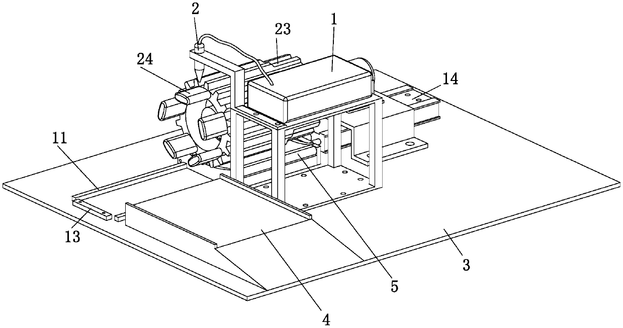
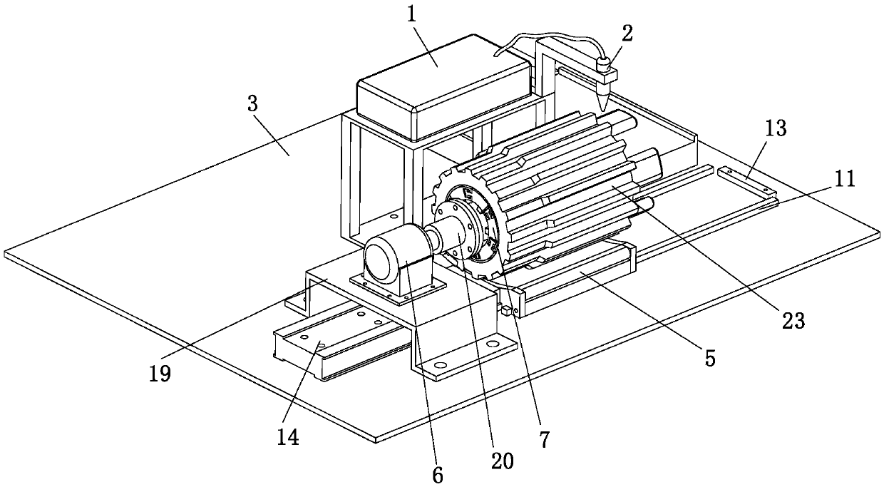
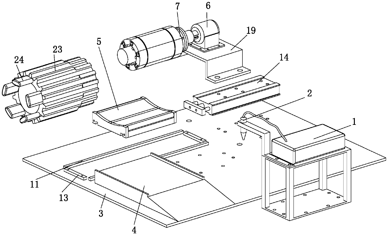
[0026] refer to Figure 1 to Figure 8 The shown automatic thermal cutting device for risers of wear-resistant sleeve castings includes a thermal cutting machine 1, and also includes a horizontally arranged base plate 3, a feeding trough 4, a material transfer mechanism and a uniform rotation mechanism, and the feed trough 4 and material transfer mechanism and the uniform rotation mechanism are all arranged on the top of the base plate 3, the material transfer mechanism includes a casting support table 5 that can move horizontally on the top of the base plate 3, the top of the casting support table 5 is a rotatable concave arc surface structure, and the concave arc surface structure The axis and the axis of the wear-resistant sleeve 23 are located in the same vertical plane, the casting support table 5 is located at ...


PUM


Abstract

The present invention relates to the field of casting processing, and more particularly to an automatic thermal cutting apparatus for a riser of an abrasion-resistant sleeve casting. The automatic thermal cutting apparatus comprises a thermal cutting machine, a horizontally arranged substrate, a feeding trough, a material moving mechanism, and a uniform rotation mechanism. The material moving mechanism comprises a casting supporting table. The uniform rotation mechanism comprises a driving motor and a casting fastening component, wherein the casting fastening component comprises an air shaft and a plurality of arc-shaped snap plates disposed outside the air shaft in a sleeving manner; all the arc-shaped snap plates are connected end to end so as to form a hollow cylindrical structure thatis disposed outside the air shaft in a sleeving manner; and the end portions of exterior walls of all the arc-shaped snap plates are sleeved with elastic snap members. An abrasion-resistant sleeve iscoaxial with the drive motor when placed on the casting supporting table, and a cutting head of the thermal cutting machine is located above a riser root of the abrasion-resistant sleeve. According tothe automatic thermal cutting apparatus for a riser of an abrasion-resistant sleeve casting, the riser of the abrasion-resistant sleeve casting can be automatically and thermally cut, time and manpower are significantly saved, and applicability of the automatic thermal cutting apparatus is high.

Description

technical field [0001] The invention relates to the field of casting processing, in particular to an automatic thermal cutting device for wear-resistant sleeve casting risers. Background technique [0002] In the process of metal casting, due to the needs of the process, in addition to the shape and specifications of the workpiece itself, the body of the casting also has some "redundant" structural parts. This part is usually called the pouring riser, and the riser refers to In order to avoid casting defects, the supplementary part added to the top or side of the casting, the function is in the casting mold, the cavity of the riser is the cavity for storing liquid metal, and the metal is supplied when the casting is formed, which can prevent shrinkage cavity and porosity , Exhaust and slag collection, while the main function of the riser is feeding. [0003] The common methods of removing sprues are physical cutting methods, including hot cutting methods such as flame, plas...

Claims


Application Information

Patent Timeline
IPC IPC(8): B23K26/38B23K26/70B23K26/08B23K37/053B23K7/00B23K7/10B22D31/00
CPCB23K26/38B22D31/00B23K7/00B23K7/10B23K26/0823B23K26/702B23K37/0531B23K37/0538
Inventor 赵飞文徐东贺甜甜戴红焱朱国伟戴玉华季茂亮石勇
Owner JIANGSU XINGYUAN POWER PLANT & METALLURGICAL EQUIP MFG
Why Eureka
Try Eureka