
Cyclone mechanical cooling equipment

A technology of cooling equipment and cyclone, applied in lighting and heating equipment, mobile duct type heat exchanger, indirect heat exchanger, etc., can solve the problem of poor dust cooling effect, save power, better cooling effect, dust removal better effect

Active Publication Date: 2018-10-19
GUIZHOU HUANKE ENVIRONMENT ECOLOGICAL RES & DEV CO LTD
View PDF6 Cites 5 Cited by
  • Summary
  • Abstract
  • Description
  • Claims
  • Application Information

AI Technical Summary

Problems solved by technology

[0005] The purpose of the present invention is to provide a cyclone mechanical cooling device to solve the problem that the cooling pipe of the mechanical cooling device is not in full contact with the dust-containing gas, and the cooling effect of the device on the dust is poor

Method used


Image

  • Cyclone mechanical cooling equipment
  • Cyclone mechanical cooling equipment
  • Cyclone mechanical cooling equipment

Examples

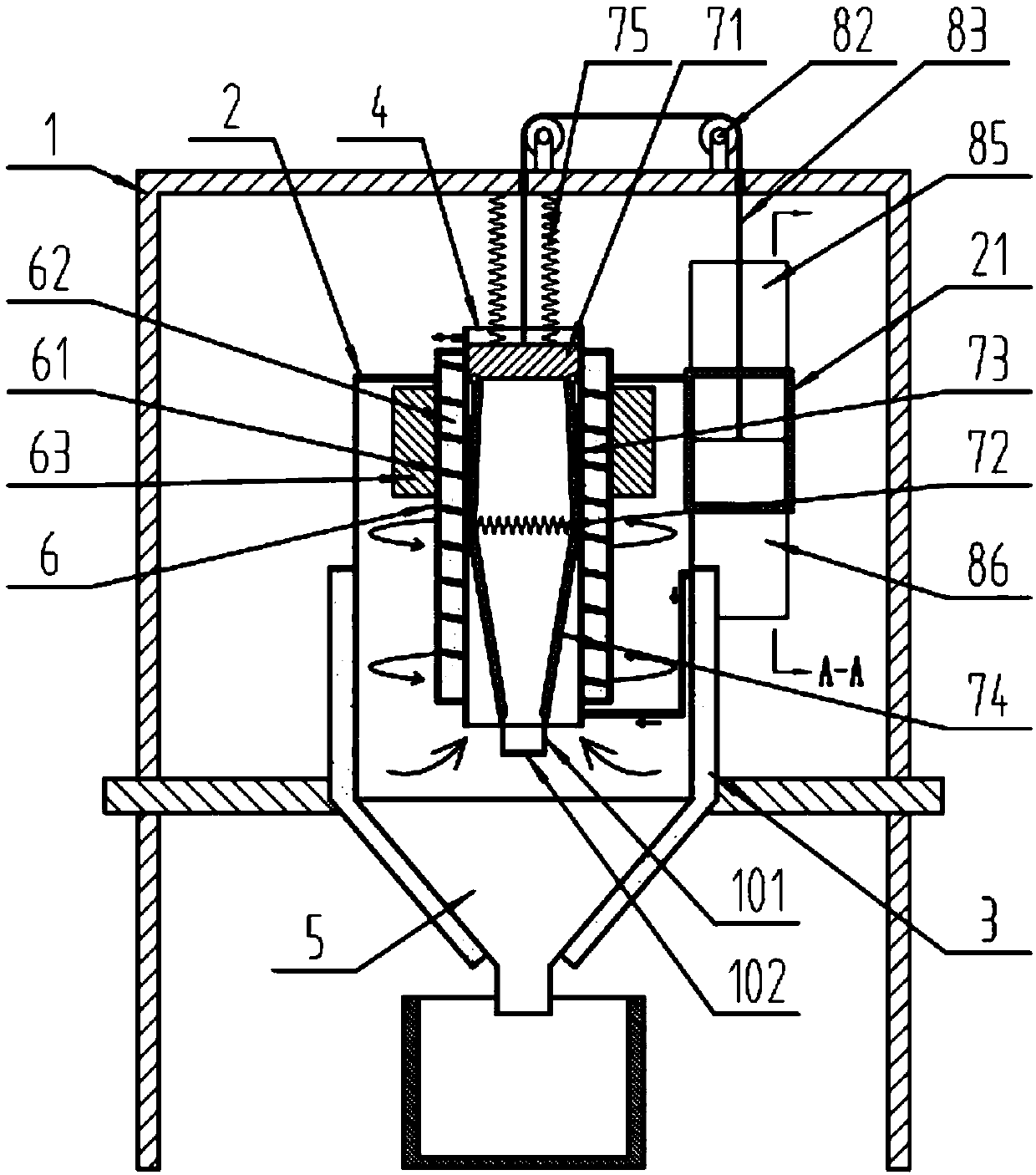
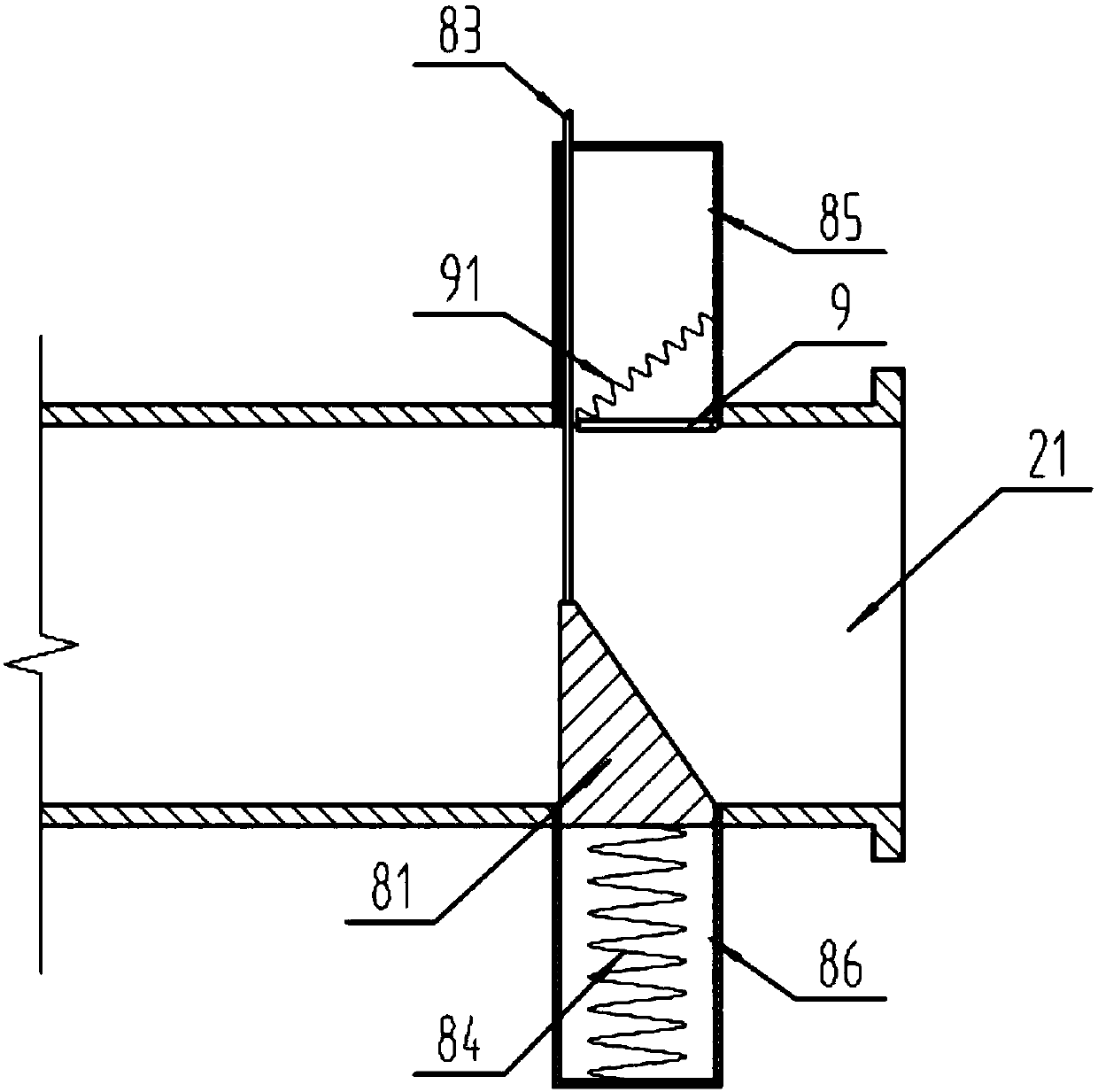
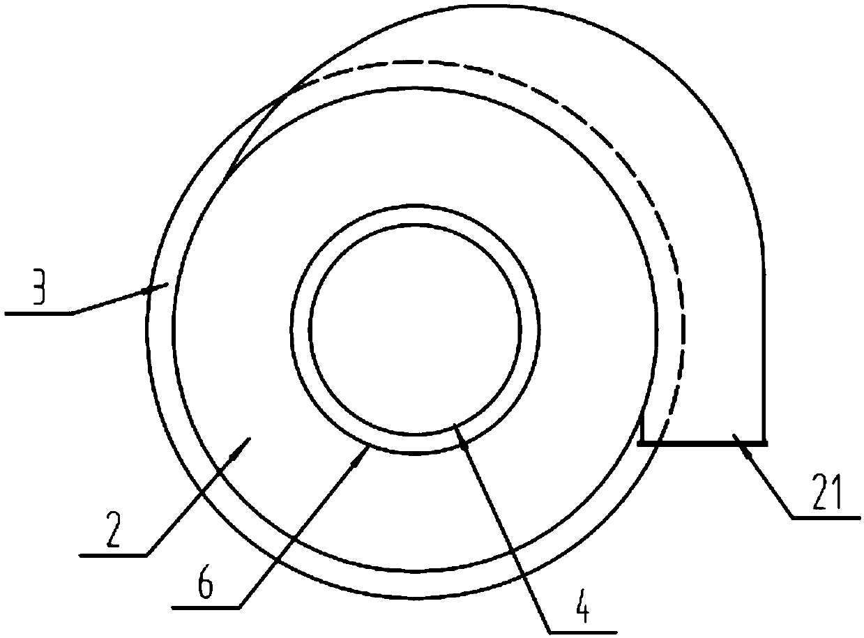

Embodiment Construction

[0026] The present invention will be described in further detail below by means of specific embodiments:

[0027] The reference signs in the drawings of the description include: support frame 1, outer cylinder 2, air inlet pipe 21, cooling cylinder 3, air outlet pipe 4, dust removal ash hopper 5, rotating drum 6, liquid delivery screw 61, cooling chamber 62, Rotating blade 63, connecting block 71, the first compression spring 72, the first articulation lever 73, the second articulation lever 74, the third compression spring 75, wedge block 81, steering wheel 82, connecting rope 83, the second compression spring 84, Buffer groove 85 , sliding groove 86 , windshield 9 , extension spring 91 , third hinged rod 101 , and horizontal pushing block 102 .

[0028] Such as Figure 1-3 As shown, the cyclone mechanical cooling equipment includes a support frame 1, an outer cylinder 2 is arranged on the support frame 1, an air inlet pipe 21 is provided on the upper part of the outer cylin...


PUM


Abstract

The invention belongs to the technical field of environment protection equipment and in particular discloses cyclone mechanical cooling equipment. The cyclone mechanical cooling equipment comprises asupporting frame, wherein an outer barrel is arranged on the supporting frame; an air inlet pipe is arranged at the upper part of the outer barrel; a cooling barrel sleeves the outer barrel; a liquidinlet pipe is arranged at the bottom of the cooling barrel; a hole is formed in the top of the outer barrel; the outer barrel is internally provided with an air outlet pipe which stretches out of thetop of the outer barrel; a dust removing ash bucket is arranged at the bottom of the outer barrel; a rotary barrel sleeves the air outlet pipe; the rotary barrel is sealed and is connected onto the air outlet pipe in a horizontal sliding manner; a liquid feeding spiral is arranged on an inner side wall of the rotary barrel; a cooling chamber is formed between the rotary barrel and the air outlet pipe; the bottom of the cooling chamber is communicated with the top of the cooling barrel; a liquid outlet pipe, which is communicated with the cooling chamber, is arranged at the upper part of the air outlet pipe; a rotary blade is arranged at the upper part in the peripheral direction of the rotary barrel. The cooling equipment has a relatively good cooling effect on dust-containing gas and a relatively excellent dust-containing effect.

Description

technical field [0001] The invention belongs to the technical field of environmental protection equipment, and specifically discloses a cyclone power cooling equipment. Background technique [0002] At present, metallurgy, building materials, electric power, chemical industry and other industries often use bag filter to remove high-temperature dust in industrial furnaces to meet emission standards. Because the dust produced by industrial furnaces has the characteristics of large amount, high dust concentration and high dust temperature, in the dust removal system, it is necessary to use a large number of mechanical cooling equipment to reduce the dust temperature to the allowable working temperature of the bag filter bag Inside. [0003] The existing mechanical cooling equipment is connected to the bag filter through a connecting pipe. The dust-containing gas is pre-dusted and cooled through the mechanical cooling equipment, and then enters the bag filter through the connec...

Claims


Application Information

Patent Timeline
IPC IPC(8): B01D45/14B01D45/18F28D11/02
CPCB01D45/14B01D45/18F28D11/02
Inventor 张朝友赵明伦袁志勇袁世国
Owner GUIZHOU HUANKE ENVIRONMENT ECOLOGICAL RES & DEV CO LTD
Learn More