
Laser interferometer mirror shape measurement method and photolithography device

A laser interferometer and topography measurement technology, applied in the field of semiconductors, can solve the problems such as the inability to completely eliminate the substrate topography error and inaccurate measurement results, and achieve the effect of reducing the substrate measurement area and shortening the time spent on calibration.

Active Publication Date: 2019-11-22
SHANGHAI MICRO ELECTRONICS EQUIP (GRP) CO LTD
View PDF8 Cites 0 Cited by
  • Summary
  • Abstract
  • Description
  • Claims
  • Application Information

AI Technical Summary

Problems solved by technology

However, the averaging method cannot completely eliminate the error caused by the substrate topography, and such measurement results will inevitably include changes in the substrate topography, making the measurement results inaccurate

Method used


Image

  • Laser interferometer mirror shape measurement method and photolithography device
  • Laser interferometer mirror shape measurement method and photolithography device
  • Laser interferometer mirror shape measurement method and photolithography device

Examples


Embodiment Construction

[0035] In order to make the above objects, features and advantages of the present invention more comprehensible, specific implementations of the present invention will be described in detail below in conjunction with the accompanying drawings.

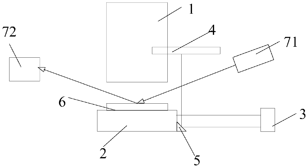
[0036] Please refer to figure 1 , the laser interferometer 3 is used to measure the vertical height and horizontal displacement of the workpiece table 2, and is generally arranged on one side of the workpiece table 2. Generally, the reflector is arranged on the workpiece table 2 and above the workpiece table 2. During the moving process of the workpiece table 2 The measurement light emitted by the laser interferometer is reflected by the mirror and returns to the laser interferometer 3, so as to calculate the real-time vertical height of the workpiece table 2. The laser interferometer 3 is equipped with two reflectors, one is a strip reflector 4 fixed on one side of the projection objective lens 1, and the other is an oblique reflector...


PUM


Abstract

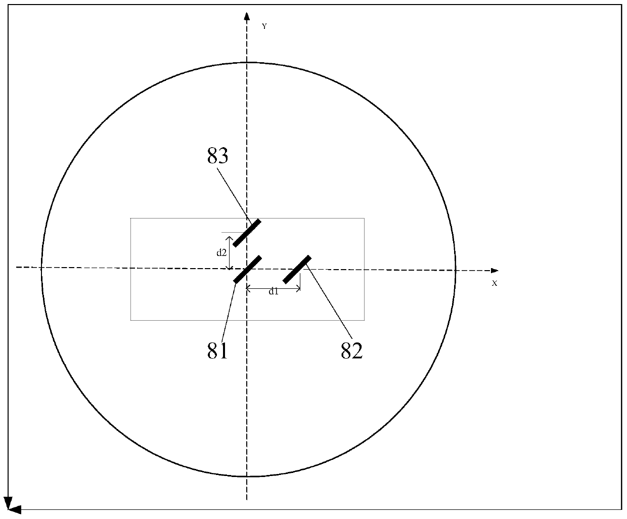
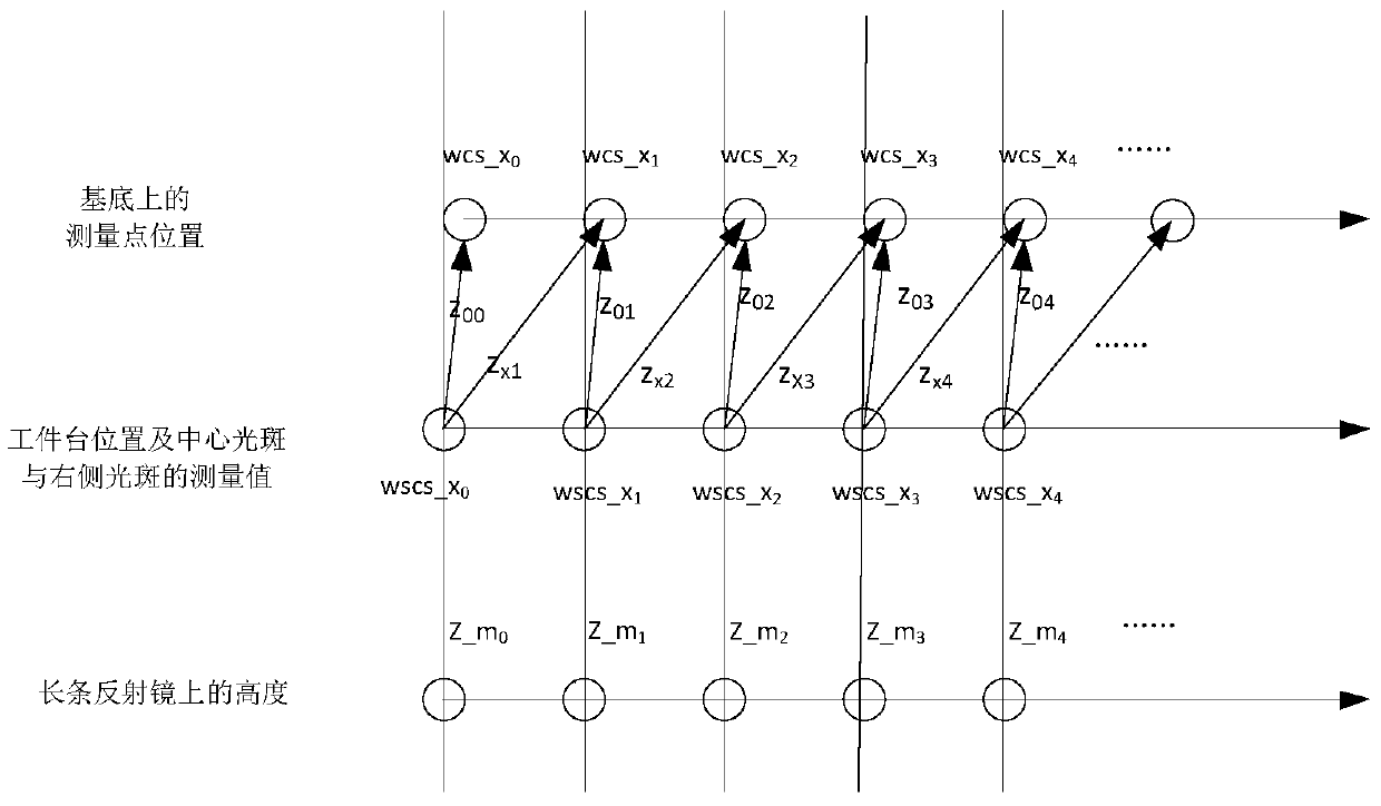
The present invention provides a method for measuring a topography of a laser interferometer reflector and a photoetching device. The measuring method comprises the following steps of: generating at least two light spots on a substrate, recording vertical heights of all light spots at the moment; moving a wafer stage several times in a same direction on a horizontal plane, moving one of the lightspots to a position where another light spot is located before moving every time the wafer stage is moved, a difference value between the vertical height of the other light spot before moving and thevertical height of the light spot after moving is a height change of a corresponding point on a long-strip mirror, and the change in height of a plurality of points on the long-strip mirror constitutes a shape change of a mirror surface of the long-strip mirror in the direction. According to the method for measuring topography of reflector of laser interferometer and the photoetching device, the standard interferometer used for calibration is removed, and the method is convenient to use on an assembled photoetching machine; at least two light spots which are not necessarily equal in spacing are arranged, so that an measurement precision is improved, and an number of light spots of FLS is not greatly increased; and an substrate measurement area is reduced, so as to shorten the time spent for calibration.

Description

technical field [0001] The invention relates to the field of semiconductors, in particular to a method for measuring the shape of a laser interferometer mirror and a photolithography device. Background technique [0002] A projection lithography machine is a device that projects the pattern on the mask onto the upper surface of the substrate through a projection objective lens. [0003] In the exposure process, the substrate is a kind of substrate, and the substrate will be uploaded to the workpiece table and reach the designated position through the movement of the workpiece table, and the workpiece table is usually positioned by a laser interferometer. The shape of the mirrors of laser interferometers, including strip mirrors and oblique mirrors, will affect the measured value of the interferometer, thereby affecting the positioning of the workpiece table. The general oblique reflector is a 45° reflector. [0004] There are many different technical solutions in the prior...

Claims


Application Information

Patent Timeline
Patent Type & Authority Patents(China)
IPC IPC(8): G03F7/20G01B11/24
CPCG01B11/2441G03F7/7085
Inventor 黄阳韩春燕王献英
Owner SHANGHAI MICRO ELECTRONICS EQUIP (GRP) CO LTD
Learn More