
A Lidar System Based on DWDM

A technology of laser radar and optics, applied in the direction of radio wave measurement system, electromagnetic wave reradiation, instruments, etc., can solve the problems of limiting laser radar detection efficiency, achieve the effect of improving photon technology rate, improving detection efficiency, and reducing system noise

Active Publication Date: 2022-05-13
江苏光在科技有限公司
View PDF8 Cites 0 Cited by
  • Summary
  • Abstract
  • Description
  • Claims
  • Application Information

AI Technical Summary

Problems solved by technology

However, for the existing high-power lidar system, the detection efficiency of the lidar is limited due to the saturation effect of the detector

Method used


Image

  • A Lidar System Based on DWDM
  • A Lidar System Based on DWDM

Examples


Embodiment 1

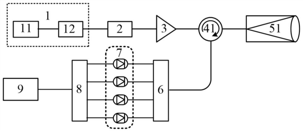
[0034] Such as figure 1 As shown, Embodiment 1 of the present invention provides a DWDM-based laser radar system, including: a light source module 1, a filter module 2, an optical amplification module 3, an optical transceiver module, a dense wavelength division multiplexing module DWDM module 6, and a detector Module 7, data acquisition module 8 and data processing module 9, wherein:

[0035] The light source module 1 is used to output laser beams;

[0036] In one embodiment of the present invention, the light source module 1 includes a continuous light source 11 and a pulse generator 12 . In another embodiment, the light source module 1 may be a pulsed laser.

[0037] The filter module 2 is used to filter the light beam emitted by the light source module 1;

[0038] The optical amplification module 3 is used to amplify the laser output from the filter module 1 and input it to the optical transceiver module;

[0039] The optical transceiver module is used to output the in...

Embodiment 2

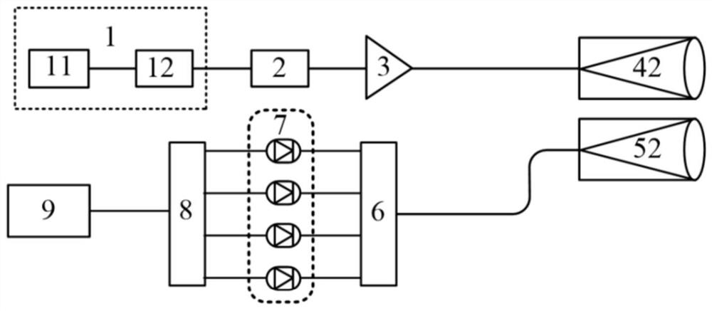
[0075] Such as figure 2 As shown, Embodiment 2 of the present invention provides a DWDM-based laser radar system. The main difference between Embodiment 2 and Embodiment 1 is that the optical transceiver module of Embodiment 2 is different from Embodiment 1. Including: light source module 1, filtering module 2, optical amplification module 3, optical transceiver module, dense wavelength division multiplexing module DWDM module 6, detector module 7, data acquisition module 8 and data processing module 9, wherein:

[0076] The light source module 1 is used to output laser beams;

[0077] In one embodiment of the present invention, the light source module 1 includes a continuous light source 11 and a pulse generator 12 . In another embodiment, the light source module 1 may be a pulsed laser.

[0078] The filter module 2 is used to filter the light beam emitted by the light source module 1;

[0079] The optical amplification module 3 is used to amplify the laser output from th...


PUM


Abstract

The invention discloses a laser radar system based on DWDM. The DWDM module of the invention divides the input laser signal into N signal outputs; the detector module includes N detectors, and the N detectors and N outputs of the DWDM module corresponding to the connection. The invention proposes a wide-spectrum laser light source at the transmitting end and a DWDM laser radar solution at the receiving end. By using a wide-spectrum light source, on the one hand, the laser emission power is increased, and on the other hand, the requirements of the radar on the light source are reduced, and the cost is reduced. By using the DWDM module, on the one hand, the photon technology rate of the laser radar system receiving signals is greatly improved, and the detector saturation effect of high-power signals is reduced. On the other hand, the noise of the laser radar is reduced, and the signal-to-noise ratio of detection is improved.

Description

technical field [0001] The invention relates to a laser radar system, in particular to a DWDM-based laser radar system. Background technique [0002] Lidar is an active modern optical remote sensing technology, which is the product of the combination of traditional radar technology and modern laser technology. Laser has the characteristics of high brightness, high directivity, high coherence, and high peak power. Therefore, lidar has the advantages of high angular resolution, high distance resolution, high time resolution, high measurement accuracy, long detection distance, multi-target detection, and strong anti-interference. By using laser as an information carrier, lidar can carry information with amplitude, frequency, phase, and polarization. Therefore, it can not only accurately measure distance, but also accurately measure frequency shift, angle, attitude, and depolarization. Following microwave radar, lidar increases the frequency of radiation sources to optical fr...

Claims


Application Information

Patent Timeline
Patent Type & Authority Patents(China)
IPC IPC(8): G01S7/481G01S17/88
CPCG01S7/4811G01S17/88
Inventor 夏和娣张苏黄允芳
Owner 江苏光在科技有限公司
Learn More