
Testing board and method for adjusting and calibrating position of probe

A test method and test board technology, applied in the ICT field, can solve problems such as low efficiency in adjusting probes, and achieve the effect of improving efficiency and achieving simplicity

Inactive Publication Date: 2018-10-16
FU TAI HUA IND SHENZHEN +1
View PDF9 Cites 2 Cited by
  • Summary
  • Abstract
  • Description
  • Claims
  • Application Information

AI Technical Summary

Problems solved by technology

[0003] In view of the above, it is necessary to provide a test board and a test method for adjusting the position of the probe to solve the problem of low efficiency of the probe adjustment

Method used


Image

  • Testing board and method for adjusting and calibrating position of probe
  • Testing board and method for adjusting and calibrating position of probe
  • Testing board and method for adjusting and calibrating position of probe

Examples


Embodiment Construction

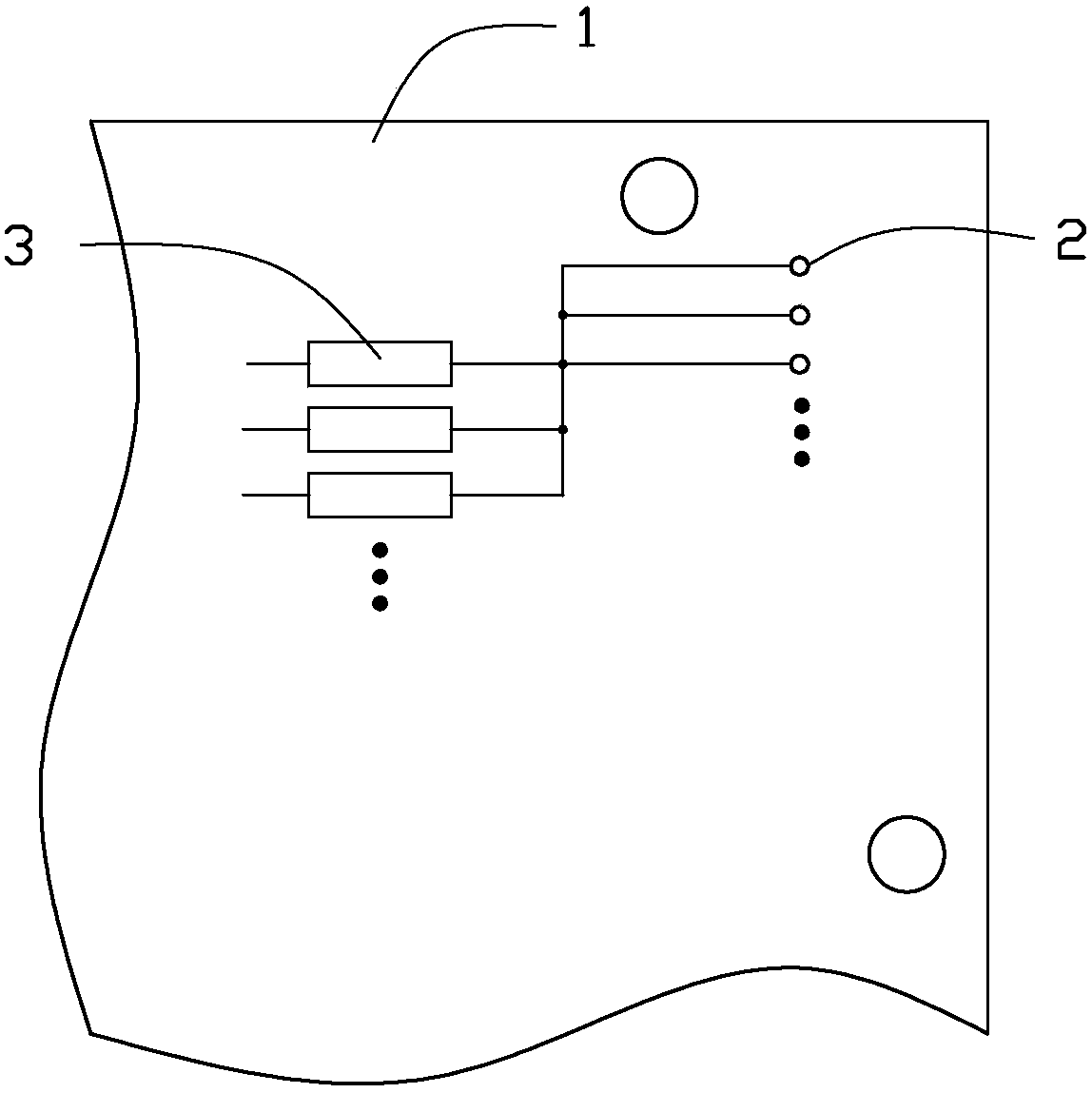
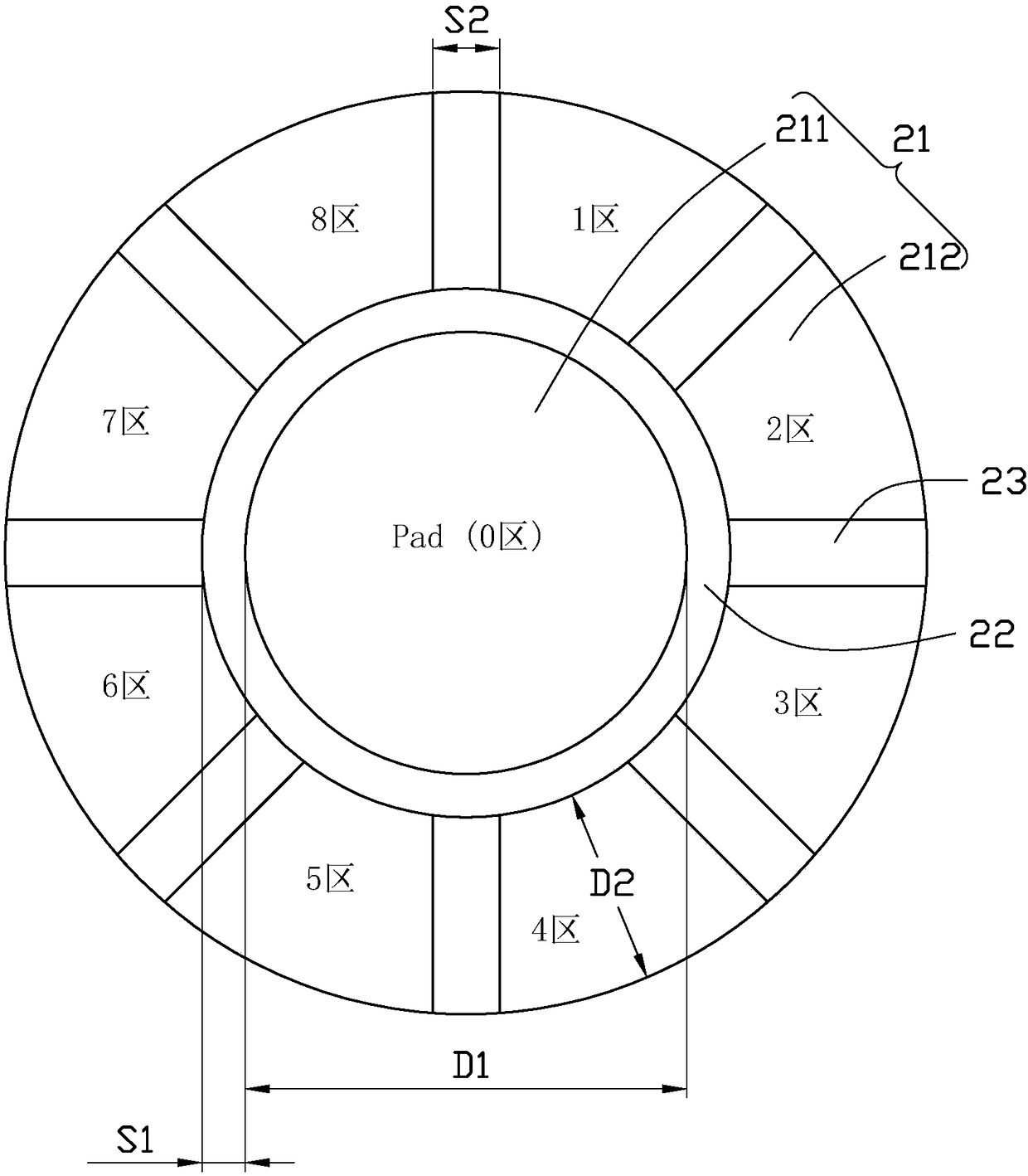
[0022] Please refer to figure 1 , is a schematic diagram of the test board 1 for adjusting the position of the probes in an embodiment of the present invention. The test board 1 includes at least one test point 2 . The test point 2 is used to test the probes of the test fixture (not shown in the figure). Please also refer to figure 2 , is a schematic diagram of test points in an embodiment of the present invention. The test point 2 includes a plurality of test areas 21 with conductive function. Each test area 21 is connected to a resistor 3 with different resistance. The plurality of test areas 21 are divided into a first test area 211 and a plurality of second test areas 212 . The plurality of second test areas 212 are arranged around the first test area 211 to surround the first test area 211 . In this embodiment, the plurality of second test areas 212 are evenly distributed around the first test area 211 . The test point 2 also includes a first insulating region 22 ...


PUM


Abstract

The invention discloses a testing board for adjusting and calibrating the position of a probe, and the testing board includes at least one test point for testing the probe, wherein the test point includes a plurality of test areas having conductive functions, and all test areas are connected with resistors with different resistances. The plurality of test areas comprise the first test area and a plurality of second test areas, wherein the plurality of second test areas are disposed around the first test area to surround the first test area. The test point further includes a first insulation area and a plurality of second insulation areas. The first test area is spaced apart from the plurality of second test areas by the first insulation region, and each two of the plurality of second testareas are spaced apart by one second insulation region. The invention also relates to a testing method for adjusting and calibrating the position of the probe. The board and method are simple in implementation, and can effectively improve the adjustment and calibration efficiency of the probe.

Description

technical field [0001] The invention relates to the field of ICT (In Circuit Test, circuit on-line test), in particular to a test board and a test method for adjusting the position of ICT fixture probes. Background technique [0002] In the prior art, when the probes on the ICT test fixture are misaligned, it is difficult for technicians to grasp the deviation direction and distance of the probes, which causes relevant technicians to spend a lot of time adjusting the positions of the probes. Reduced probe tuning efficiency. Contents of the invention [0003] In view of the above, it is necessary to provide a test board and a test method for adjusting the position of probes to solve the problem of low efficiency of adjusting probes. [0004] A test board for adjusting the position of probes, including at least one test point for testing probes, the test point includes a plurality of test areas with conductive functions, each test area is connected to resistors of different...

Claims


Application Information

Patent Timeline
Patent Type & Authority Applications(China)
IPC IPC(8): G01R35/00
CPCG01R35/005G01R31/2818G01R31/2884G01R31/2891
Inventor 刘宇青杨炜达侯晓峰梁国栋
Owner FU TAI HUA IND SHENZHEN
Learn More