Smart card, smart card control method and device and equipment
A smart card and smart card chip technology, applied in the field of smart cards, can solve problems that easily affect the stability of smart card communication, and achieve the effect of improving communication accuracy and ensuring stability
- Summary
- Abstract
- Description
- Claims
- Application Information
AI Technical Summary
Problems solved by technology
Method used
Image

Examples
Embodiment 1
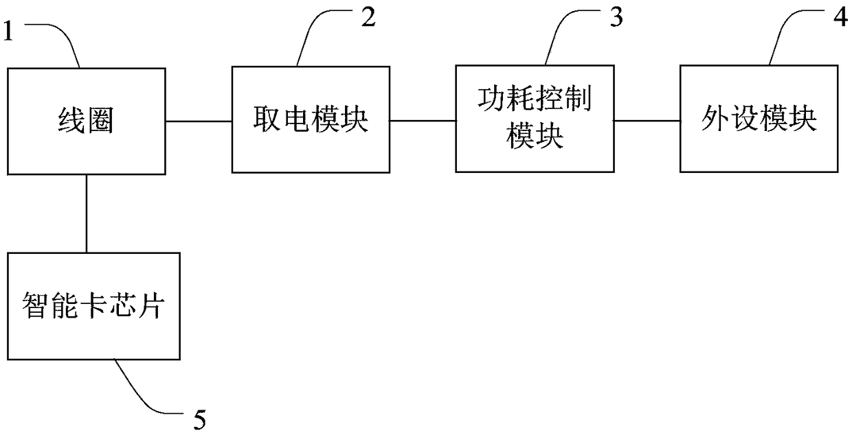
[0045] Embodiment 1 of the present invention provides a smart card. figure 1 It is a structural block diagram of the smart card provided by Embodiment 1 of the present invention. like figure 1 As shown, the smart card in this embodiment includes: a coil 1, a power-taking module 2, a power consumption control module 3, a peripheral module 4, and a smart card chip 5;
[0046] The input terminal of the power-taking module 2 is connected to the coil 1 for converting the AC power received from the coil 1 into DC power;
[0047] The output terminal of the power-taking module 2 is connected to the peripheral module 4 through the power consumption control module 3;
[0048] The power consumption control module 3 is used to control the power consumption of the peripheral module 4;
[0049] The smart card chip 5 is connected to the coil 1. When performing non-contact communication, the smart card is placed in the radio frequency field of the card reader. The smart card chip 5 can tak...
Embodiment 2
[0067] Embodiment 2 of the present invention provides a smart card. In this embodiment, on the basis of the technical solution provided in Embodiment 1, the power consumption control is realized through a constant current diode.
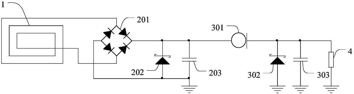
[0068] figure 2 It is a schematic circuit diagram of the smart card provided by Embodiment 2 of the present invention. like figure 2 As shown, the smart card in this embodiment includes: a coil 1 , a power acquisition module, a power consumption control module, and a peripheral module 4 .
[0069] In this embodiment, the power consumption control module includes a constant current diode 301 , through which the input current of the peripheral module 4 can be controlled.
[0070] The solution in this embodiment is applicable to the situation where the input voltage is constant (the input voltage has undergone voltage stabilization conversion; or when the load current is constant, the input voltage is also constant).
[0071] Optionally, the power...
Embodiment 3
[0078] Embodiment 3 of the present invention provides a smart card. In this embodiment, on the basis of the technical solution provided in Embodiment 2, a linear voltage regulator is added to realize voltage control.
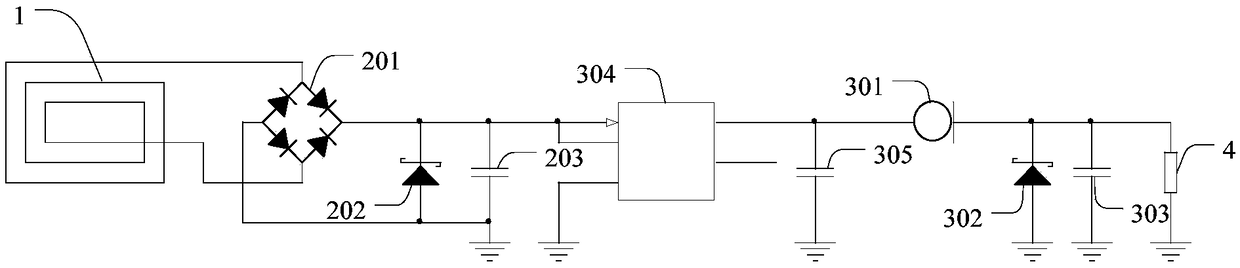
[0079] image 3 It is a schematic circuit diagram of a smart card provided by Embodiment 3 of the present invention. like image 3 As shown, the smart card in this embodiment includes: a coil 1 , a power acquisition module, a power consumption control module, and a peripheral module 4 .
[0080] In this embodiment, the power consumption control module includes a constant current diode 301 and a linear voltage regulator 304, the input end of the linear voltage regulator 304 is connected to the power-taking module, and the output end is connected to the constant current diode 301 Connection, can realize the function of stabilizing the voltage.
[0081] The linear voltage regulator 304 can adopt an LDO (low dropout regulator, low dropout linear voltage regulato...
PUM
 Abstract
Description
Claims
Application Information
 - Generate Ideas
- Intellectual Property
- Life Sciences
- Materials
- Tech Scout
- Unparalleled Data Quality
- Higher Quality Content
- 60% Fewer Hallucinations
Browse by: Latest US Patents, China's latest patents, Technical Efficacy Thesaurus, Application Domain, Technology Topic, Popular Technical Reports.
© 2025 PatSnap. All rights reserved.Legal|Privacy policy|Modern Slavery Act Transparency Statement|Sitemap|About US| Contact US: help@patsnap.com