
Digital printing and air sucking device and digital printing machine

A digital printing machine and air suction device technology, which is applied in printing devices, printing, etc., can solve the problems of easy stranding of the medium, and achieve the effects of avoiding single-point drying, expanding the suction area, and increasing the drying speed

Pending Publication Date: 2018-10-12
SHENZHEN RUNTIANZHI DIGITAL EQUIP
View PDF17 Cites 7 Cited by
  • Summary
  • Abstract
  • Description
  • Claims
  • Application Information

AI Technical Summary

Problems solved by technology

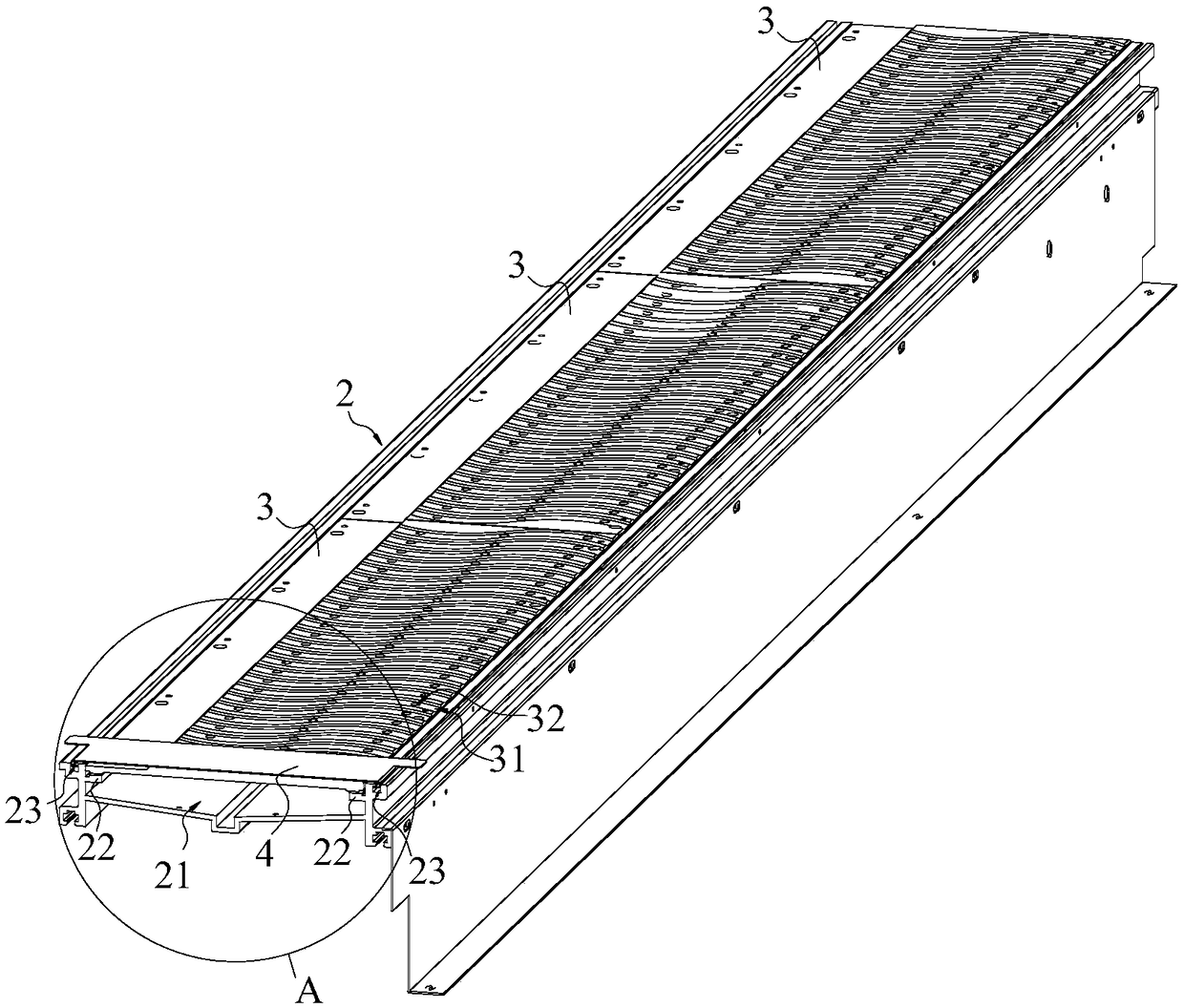
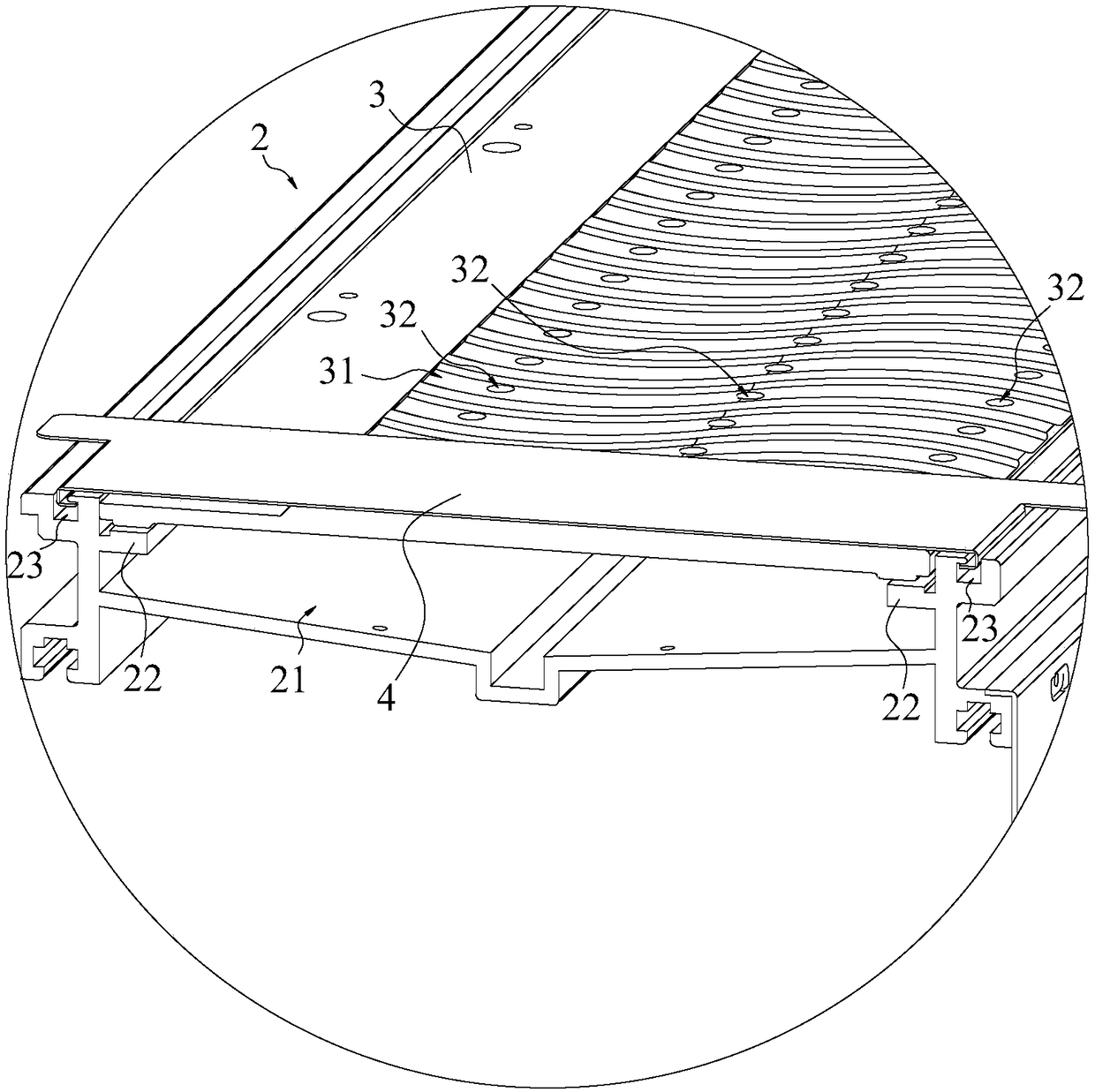
[0003] The purpose of the present invention is to provide a digital printing suction device and a digital printing machine, aiming to solve the technical problem that the medium is easy to strand when the printing or printing device of the prior art uses suction holes to dry the medium

Method used


Image

  • Digital printing and air sucking device and digital printing machine
  • Digital printing and air sucking device and digital printing machine
  • Digital printing and air sucking device and digital printing machine

Examples


Embodiment Construction

[0024] Embodiments of the present invention are described in detail below, examples of which are shown in the drawings, wherein the same or similar reference numerals designate the same or similar elements or elements having the same or similar functions throughout. The embodiments described below by referring to the figures are exemplary and are intended to explain the present invention and should not be construed as limiting the present invention.

[0025] In describing the present invention, it should be understood that the terms "length", "width", "upper", "lower", "front", "rear", "left", "right", "vertical", The orientation or positional relationship indicated by "horizontal", "top", "bottom", "inner", "outer", etc. are based on the orientation or positional relationship shown in the drawings, and are only for the convenience of describing the present invention and simplifying the description, rather than Nothing indicating or implying that a referenced device or element...


PUM

PropertyMeasurementUnit
Depthaaaaaaaaaa

Abstract

The invention belongs to the technical field of printing equipment, and in particular, relates to a digital printing and air sucking device and a digital printing machine. The digital printing and airsucking device comprises a printing platform and an air sucking cover plate; the printing platform is provided with a negative-pressure groove; the air sucking cover plate covers the negative-pressure groove, and is provided with multiple air sucking runners arranged side by side; each air sucking runner extends in a moving direction of a medium in a wave or sawtooth form; and multiple air sucking holes arranged in each air sucking runner in the extension direction. The air sucking area of the air sucking holes is changed from a hole form to a whole air sucking runner, so that the air suckingarea of the air sucking holes is increased, and the medium can be dried more uniformly; the dried medium is more smooth and not easy to drape; meanwhile, the drying speed is accelerated; and gaps between the runners can level the medium, so that the areas, recessed into the air sucking runners, of the medium can be leveled by the gaps between the runners during drying and curing, and the medium can be cured more smoothly and is not easy to drape.

Description

technical field [0001] The invention belongs to the technical field of printing equipment, and in particular relates to a digital printing air suction device and a digital printing machine. Background technique [0002] In the printing or printing device, the thermal transfer paper passes through the printing platform, and the print head ejects a large amount of ink onto the thermal transfer paper according to the pattern to be printed. The shrinkage force and tension of the paper after absorbing ink change, and the thermal transfer paper is The flatness of the printing area changes, causing the thermal transfer paper to curl up and become uneven. After the thermal transfer paper is stranded, the ink is sprayed onto the thermal transfer paper, which will easily lead to the deformation of the printed pattern and the printing ghost, making the printing unclear. The usual method is to set up a suction hole on the printing platform, and the suction hole sucks the air, and at th...

Claims


Application Information

Patent Timeline
IPC IPC(8): B41J11/00
CPCB41J11/0005B41J11/0015B41J11/0085B41J11/06
Inventor 李力兰西余茂基江洪
Owner SHENZHEN RUNTIANZHI DIGITAL EQUIP
Learn More