An industrial flue gas desulfurization and denitrification equipment

A technology for desulfurization, denitrification, and industrial flue gas, which is applied in gas treatment, separation methods, and separation of dispersed particles. It can solve the problems of limited contact area between water and flue gas, insufficient mixing, and low reaction efficiency. The effect of increasing the contact area and prolonging the flow path

Active Publication Date: 2021-03-12
佛山市奥瑞斯科技有限公司
View PDF6 Cites 2 Cited by
  • Summary
  • Abstract
  • Description
  • Claims
  • Application Information

AI Technical Summary

Problems solved by technology

[0003] In daily life, because ammonia gas reacts with nitrate-containing substances without pollution, and sulfur is easily soluble in water, it is widely used in flue gas desulfurization and denitrification. However, the existing ammonia gas passes into the flue gas, and the mixing with the flue gas is not enough. Uniformity, low reaction efficiency, and when desulfurization is carried out by directly passing flue gas into water, the contact area between water and flue gas is limited, so the removal efficiency is low, and dust removal is usually carried out during the denitrification process, which may easily cause internal blockage

Method used


Image

  • An industrial flue gas desulfurization and denitrification equipment
  • An industrial flue gas desulfurization and denitrification equipment
  • An industrial flue gas desulfurization and denitrification equipment

Examples


Embodiment Construction

[0028] In order to make the technical means, creative features, goals and effects achieved by the present invention easy to understand, the present invention will be further described below in conjunction with specific embodiments.

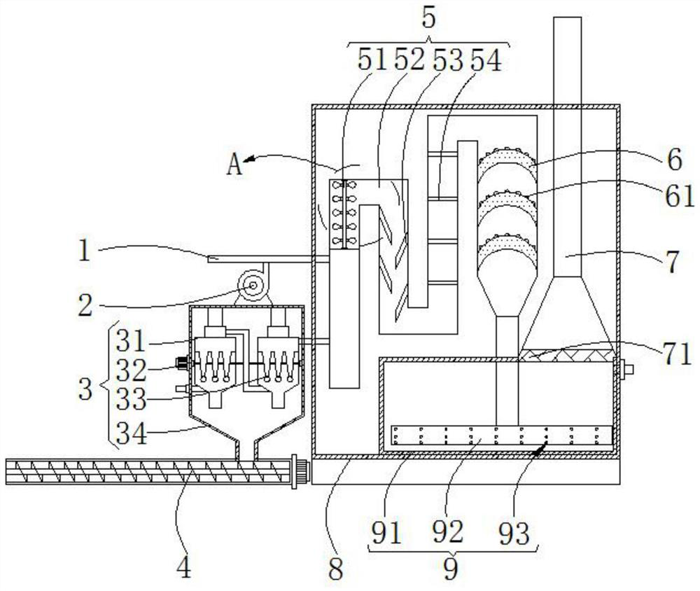
[0029] Such as figure 1As shown, a kind of industrial flue gas desulfurization and denitrification equipment according to the present invention includes ammonia gas input pipe 1, blower 2, dust removal mechanism 3, screw conveyor 4, conveying mechanism 5, catalytic plate 6, chimney 7, treatment box Body 8 and desulfurization mechanism 9, the bottom of the dust removal mechanism 3 is provided with the screw conveyor 4 for dust output, and the side of the dust removal mechanism 3 is fixed to the treatment box 8; the treatment box 8 The inside is provided with the delivery mechanism 5, and the delivery mechanism 5 communicates with the dust removal mechanism 3 and the ammonia gas input pipe 1; the side of the ammonia gas input pipe 1 communicates wit...


PUM


Abstract

The invention relates to the field of flue gas treatment, in particular to an industrial flue gas desulfurization and denitrification equipment, including ammonia gas input pipe, blower, dust removal mechanism, screw conveyor, conveying mechanism, catalytic plate, chimney, treatment box and desulfurization Mechanism; the mixture of ammonia gas and air can be fed through the ammonia gas input pipe with the blower, which is convenient for removing the nitrate in the flue gas. The dust removal mechanism can remove the dust in the flue gas to avoid blocking the subsequent reactor and remove The dust is easy to push and output through the screw conveyor. The conveying mechanism realizes the transportation and mixing of the flue gas, which is convenient for its reaction and denitrification. The catalytic plate can strengthen the catalytic reaction, and the desulfurization mechanism realizes the removal of sulfur-containing substances in the flue gas. The flue gas desulfurization and denitrification equipment of the present invention installs the dust removal mechanism before the denitrification and desulfurization equipment to prevent dust from clogging the subsequent reaction vessel, which can make the internal gas mix more evenly and react more fully when in contact with the catalytic plate with a special structure.

Description

technical field [0001] The invention relates to the field of flue gas treatment, in particular to an industrial flue gas desulfurization and denitrification equipment. Background technique [0002] Industry is an important part of the secondary industry. The development of industry promotes economic development, but it also brings environmental problems. The substances containing sulfur and nitrate in industrial flue gas are more harmful. Therefore, industrial flue gas needs to be desulfurized and denitrified. , Flue gas desulfurization and denitrification technology is a boiler flue gas purification technology applied to the chemical industry where nitrogen oxides and sulfur oxides are generated; nitrogen oxides and sulfur oxides are one of the main sources of air pollution; so this technology is applied There are many benefits to ambient air purification. [0003] In daily life, because ammonia gas reacts with nitrate-containing substances without pollution, and sulfur is...

Claims


Application Information

Patent Timeline
Patent Type & Authority Patents(China)
IPC IPC(8): B01D53/75B01D53/86B01D53/50B01D53/56B01D46/02B01D53/78
CPCB01D46/02B01D53/75B01D53/78B01D53/86B01D53/8609B01D53/8628B01D53/8631B01D2251/2062B01D2258/0283
Inventor 杨大鹏孙伦业
Owner 佛山市奥瑞斯科技有限公司
Why Eureka
Try Eureka