
Display device

A display device and resistance technology, applied in static indicators, instruments, etc., can solve the problems of product influence, overcurrent protection false triggering, etc., and achieve the effect of high protection current value

Active Publication Date: 2018-10-09
SHENZHEN CHINA STAR OPTOELECTRONICS SEMICON DISPLAY TECH CO LTD
View PDF3 Cites 3 Cited by
  • Summary
  • Abstract
  • Description
  • Claims
  • Application Information

AI Technical Summary

Problems solved by technology

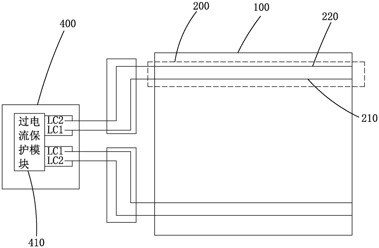
For example, in the experiment, when the short-circuit current of the first low-frequency control signal bus and the second low-frequency control signal line is 45mA, the temperature will reach 45°C, and the temperature will reach 45°C only when the short-circuit current of the two clock signal bus lines reaches 60mA. If the preset maximum temperature is 45°C, if 60mA is used as the protection current at this time, when the first low-frequency control signal bus and the second low-frequency control signal bus are short-circuited, the first low-frequency control signal bus and the second low-frequency control signal bus are short-circuited. The over-current protection will only be triggered when the current is 60mA, but at this time, the heat generated by the short circuit between the first low-frequency control signal bus and the second low-frequency control signal bus makes the temperature of the display device already exceed 45°C, which has a great impact on the product, but If the protection current is set to 45mA, it may lead to false triggering of over-current protection

Method used


Image

  • Display device
  • Display device
  • Display device

Examples


Embodiment Construction

[0026] In order to further illustrate the technical means adopted by the present invention and its effects, the following describes in detail in conjunction with preferred embodiments of the present invention and accompanying drawings.

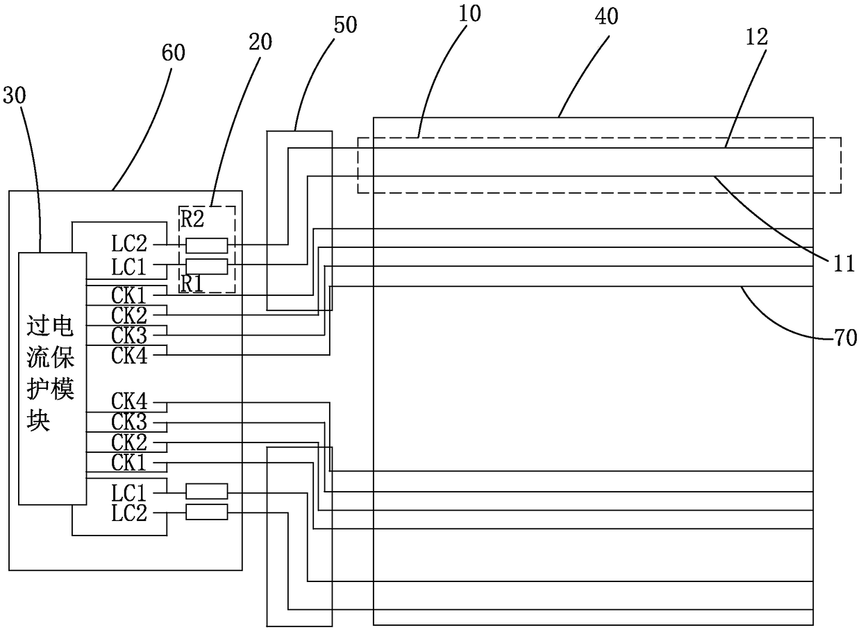
[0027] see figure 2 , the present invention provides a display device, including at least one bus group 10 , at least one resistor unit 20 and an overcurrent protection module 30 .

[0028] A resistance unit 20 corresponds to a bus group 10 . Each bus group 10 includes a first low frequency control signal bus 11 and a second low frequency control signal bus 12 . Each resistor unit 20 includes a first resistor R1 and a second resistor R2. One end of the first resistor R1 is connected to the first low-frequency control signal LC1, the other end is electrically connected to one end of the first low-frequency control signal bus 11 corresponding to the bus group 10, and one end of the second resistor R2 is connected to the second low-frequency s...


PUM


Abstract

The invention provides a display device. The display device comprises a bus group, a resistor unit and an over-current protection module, wherein one end of a first resistor of the resistor unit is connected to a first low-frequency control signal, and the other end of the first resistor is electrically connected with one end of a corresponding first low-frequency control signal bus, one end of asecond resistor is connected with a second low-frequency control signal, and the other end of the second resistor is electrically connected with one end of a corresponding second low-frequency controlsignal bus, and the sum of the resistances of the first resistor and the second resistor of each resistor unit is larger than the ratio of the difference between the high potential and the low potential of the first low-frequency control signal to the preset protection current. In this way, no matter at which position the first low-frequency control signal bus and the second low-frequency controlsignal bus are short-circuited, the current of the first low-frequency control signal bus and the current of the second low-frequency control signal bus are both smaller than the protection current,so that the protection current value is set to be higher on the premise that the temperature of the display device is not influenced.

Description

technical field [0001] The present invention relates to the field of display technology, in particular to a display device. Background technique [0002] In the field of display technology, flat panel display devices, such as Liquid Crystal Display (LCD) and Organic Light Emitting Display (OLED), are light, thin, low power consumption, high brightness and high image quality. And other advantages, occupy an important position in the field of flat panel display technology. The display device at least includes an array substrate provided with a pixel array. Generally, the display area of ​​the array substrate is provided with scan lines, data lines, and pixel electrodes located in the pixel area, and also includes a gate drive circuit located in the peripheral area or on the circuit board. and source drive circuits. [0003] At present, a gate driver on array (GOA) technology is generally used to prepare a display substrate, and a GOA circuit refers to a scanning line driving...

Claims


Application Information

Patent Timeline
Patent Type & Authority Applications(China)
IPC IPC(8): G09G3/36G09G3/3266
CPCG09G3/3266G09G3/3674
Inventor 吕晓文陈书志
Owner SHENZHEN CHINA STAR OPTOELECTRONICS SEMICON DISPLAY TECH CO LTD
Learn More