
Gas cylinder valve and gas cylinder assembly

A technology for gas cylinder valves and gas cylinders, which is applied to the direction of valves, control valves, safety valves, etc. for inflation, and can solve problems such as damage to gas cylinders and heavy workload of staff, and achieve the effect of avoiding damage

Inactive Publication Date: 2018-10-09
HENAN AEROSPACE HYDRAULIC & PNEUMATIC TECH
View PDF9 Cites 6 Cited by
  • Summary
  • Abstract
  • Description
  • Claims
  • Application Information

AI Technical Summary

Problems solved by technology

[0003] The object of the present invention is to provide a gas cylinder valve to solve the problem of heavy workload of staff and easy damage to the gas cylinder when the gas cylinder in the prior art continuously supplies gas to the outside through the gas cylinder valve; The purpose is to provide a gas cylinder assembly using the gas cylinder valve

Method used


Image

  • Gas cylinder valve and gas cylinder assembly
  • Gas cylinder valve and gas cylinder assembly
  • Gas cylinder valve and gas cylinder assembly

Examples


Embodiment Construction

[0021] Embodiments of the present invention will be further described below in conjunction with the accompanying drawings.

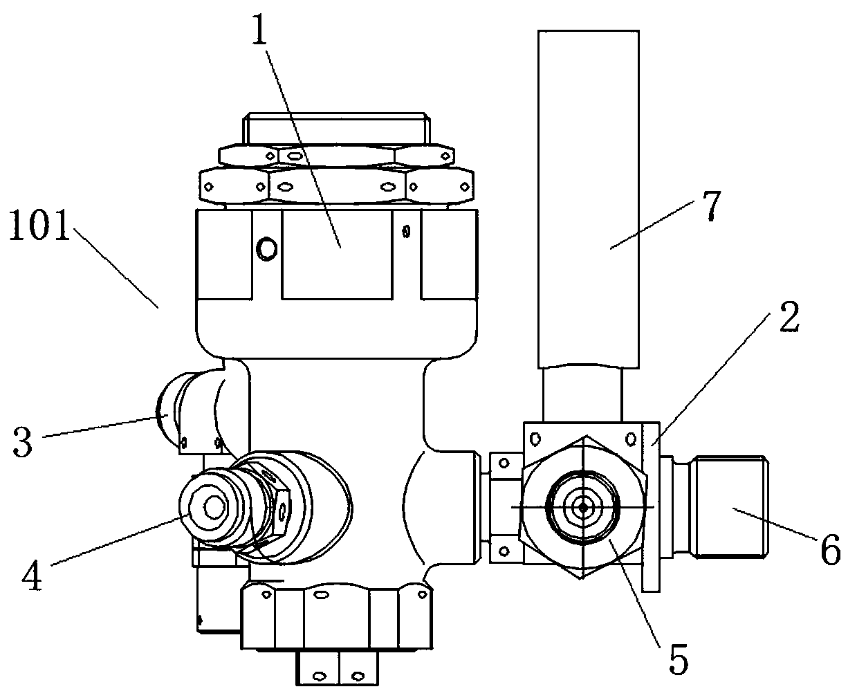
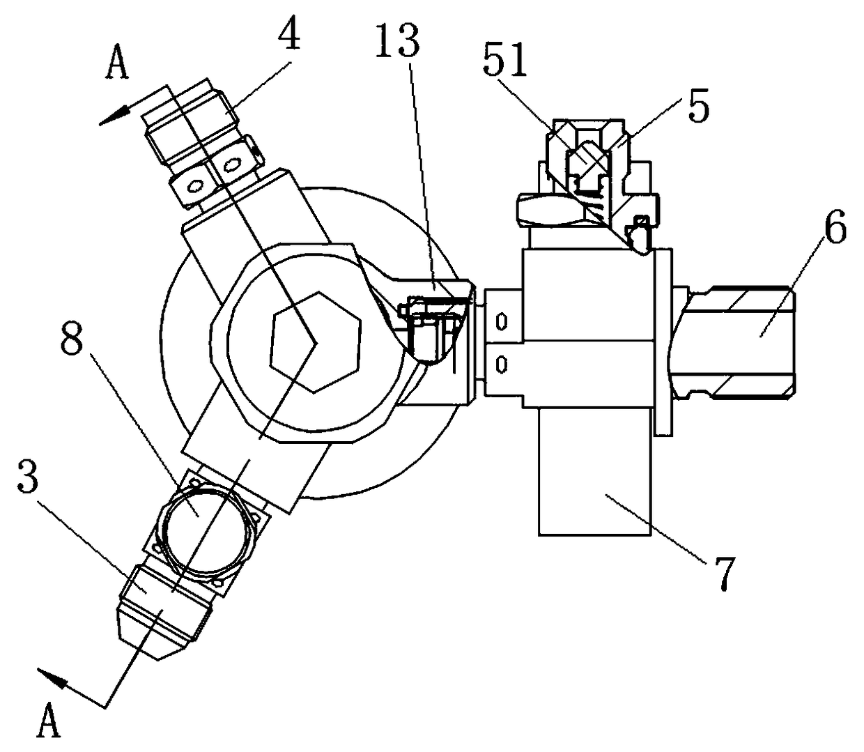
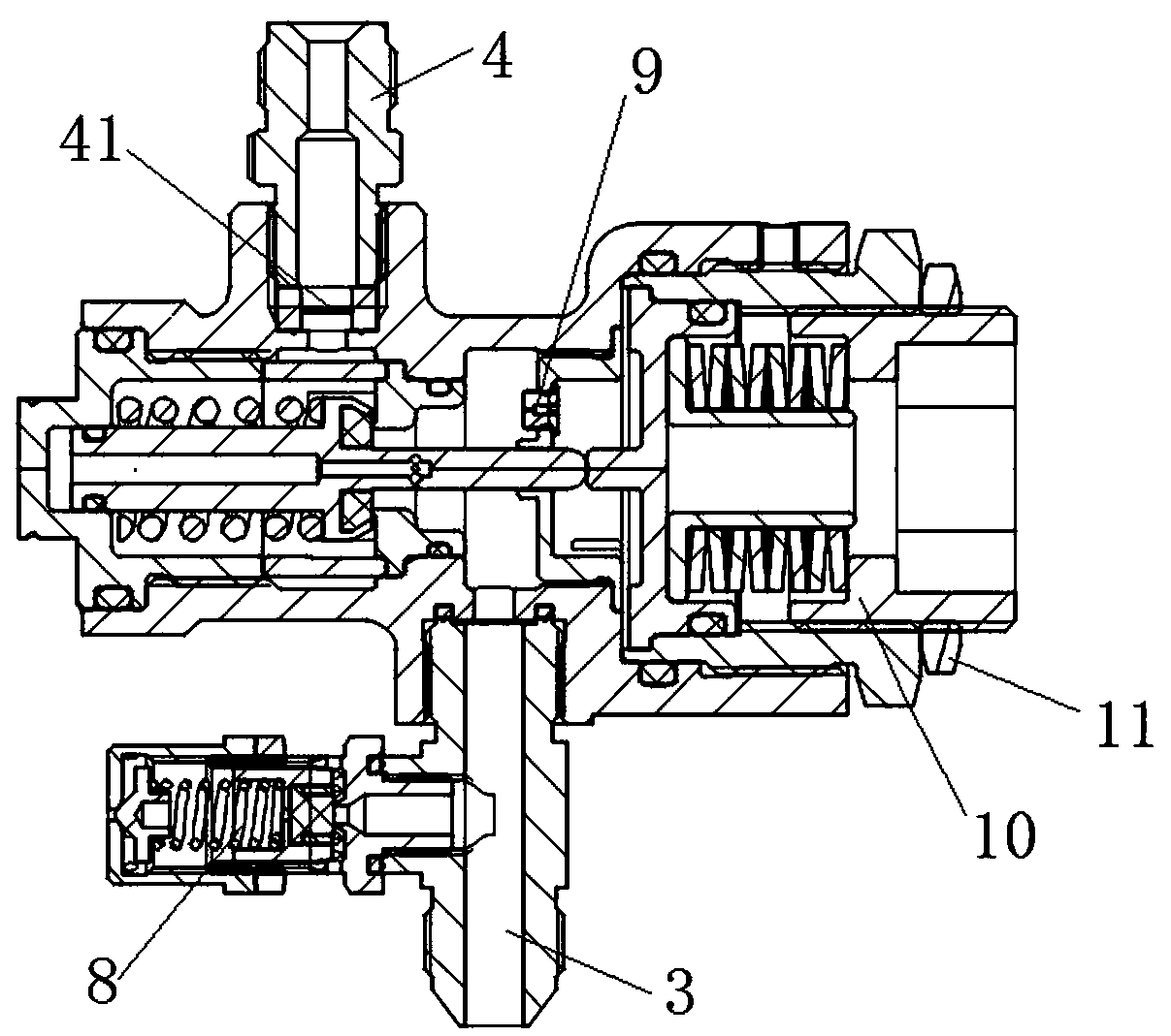
[0022] Specific embodiment 1 of the gas bottle assembly of the present invention, such as Figure 1 to Figure 4 As shown, the gas cylinder assembly includes a gas cylinder and a gas cylinder valve 101 arranged on the gas cylinder. The gas cylinder valve 101 includes a valve body, and the valve body is provided with an inflation interface 5 and a gas cylinder interface 6 communicated with the inflation interface 5. The bottle interface 6 communicates with the air inlet 13 of the pressure reducing valve body of the valve body so that the gas cylinder can supply air to the outside through the pressure reducing structure, and the air inlet 13 of the pressure reducing valve body of the valve body is provided with an air supply check valve 12 . A gas supply one-way valve is installed at the air inlet. When the gas cylinder supplies gas to the outside, if the ...


PUM


Abstract

The invention relates to a gas cylinder valve and a gas cylinder assembly. The gas cylinder valve comprises a valve body. A charging port and a gas cylinder port communicating with the inflation portand used for charging gas into a gas cylinder are formed in the valve body. A gas supply port and a gas supply channel enabling the gas supply port to communicate with the gas cylinder port are further formed in the valve body. A pressure reduction structure used for reducing the pressure of gas flowing out of the gas cylinder port is arranged on the gas supply channel. A gas supply one-way valveused for closing the gas supply channel when the pressure in the gas cylinder is lower than a set pressure value is further arranged on the gas supply channel and is located between the pressure reduction structure and the gas cylinder port. A gas supply one-way valve is arranged between the pressure reduction structure and the gas cylinder port. When the gas cylinder supplies gas to the outside,the one-way valve is closed if the pressure in the gas cylinder is lower than the set value for closing the gas supply one-way valve, so that gas in the gas cylinder is prevented from being completelydischarged, and the situation that the gas cylinder is damaged due to the fact that the pressure in the gas cylinder is low or even is negative is avoided.

Description

technical field [0001] The invention relates to a gas cylinder valve and a gas cylinder assembly. Background technique [0002] Commonly used gas cylinder valves usually have only one switch function. The gas cylinder valve and the pressure reducing valve are installed separately. When inflating, remove the pressure reducing valve and fill the gas cylinder through the gas cylinder valve. A decompression valve is installed on the valve to output the decompressed gas to the outside. From the above process, it can be seen that when inflating and delivering gas to the outside, people have to dismantle and install the decompression valve cyclically, which is more troublesome to operate and reduces work efficiency. In response to this problem, the Chinese patent with the authorized announcement number CN205534391U and the authorized announcement date of 2016.08.31 discloses a gas cylinder valve with decompression function. The bottle interface, the gas filling interface and the ...

Claims


Application Information

Patent Timeline
IPC IPC(8): F16K17/40F16K15/06F16K24/06B01D35/02
CPCB01D35/02F16K15/06F16K17/40F16K24/06
Inventor 田跃军张耀新杨凯刘宝林李继军荆兵张聪超白祥志姜银松
Owner HENAN AEROSPACE HYDRAULIC & PNEUMATIC TECH
Learn More