
Polygonal cutting tool

A cutting tool and polygonal technology, applied in the field of polygonal cutting tools, can solve problems such as difficulty in ensuring accurate change of workpiece angles, inaccurate placement of workpieces, inaccurate cutting angles, etc., so as to improve the pass rate of workpieces, avoid material waste, The effect of improving cutting efficiency

Inactive Publication Date: 2018-10-09
利辛县宝隆橡塑密封件有限责任公司
View PDF5 Cites 3 Cited by
  • Summary
  • Abstract
  • Description
  • Claims
  • Application Information

AI Technical Summary

Problems solved by technology

[0002] Cutting refers to the use of cutting tools (including cutting tools, grinding tools and abrasives) to cut off the excess material layer on the blank or workpiece into chips, so that the workpiece can obtain the specified geometric shape, size and surface quality. In the process, in the prior art, when it is necessary to cut a polygonal workpiece, it is impossible to realize one-time processing and molding, and it is often necessary to fix and cut the workpiece multiple times, which is very troublesome, and in the process of multiple fixings, it is difficult to Ensure that the angle of the workpiece is changed accurately, and it is easy to cause the cutting angle of the workpiece to be inaccurate due to the inaccurate placement angle, which makes the processed workpiece unqualified, and even causes the waste of the whole piece of material, which not only brings great harm to the processing workers Trouble, it also caused a certain loss to the factory. The inability to achieve a single fixed cutting and accurate angle change is a very difficult problem in the cutting process of polygonal workpieces. The existing technology cannot satisfy people today. Need for polygonal cutting tools that are easy to adjust, ensure accurate adjustment of the cutting angle, avoid material waste, and are simple to operate

Method used


Image

  • Polygonal cutting tool
  • Polygonal cutting tool
  • Polygonal cutting tool

Examples


Embodiment Construction

[0019] The following will clearly and completely describe the technical solutions in the embodiments of the present invention with reference to the accompanying drawings in the embodiments of the present invention. Obviously, the described embodiments are only some, not all, embodiments of the present invention. Based on the embodiments of the present invention, all other embodiments obtained by persons of ordinary skill in the art without making creative efforts belong to the protection scope of the present invention.

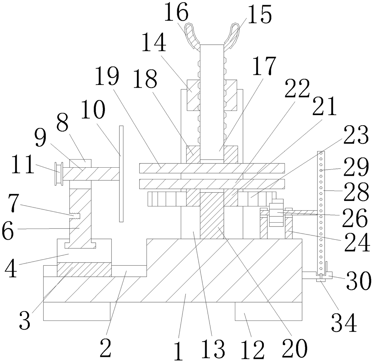
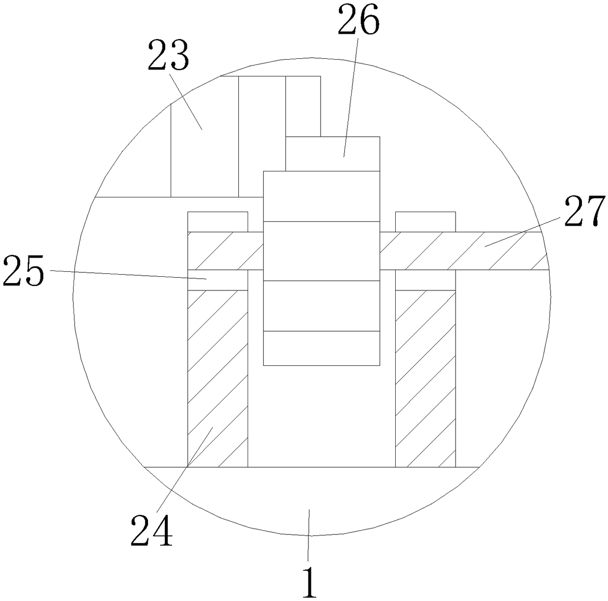
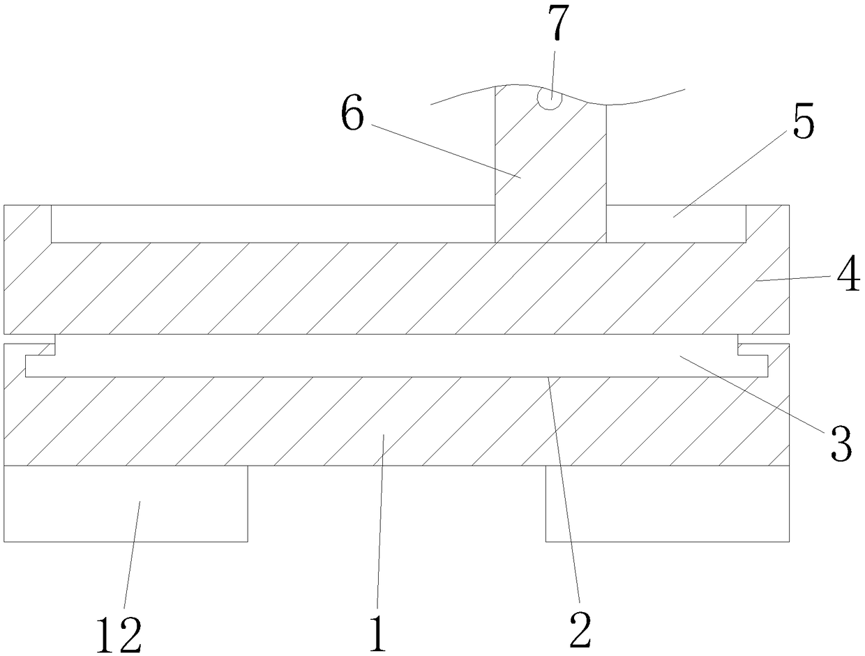
[0020] see Figure 1-5 , the present invention provides a technical solution: a polygonal cutting tool, including a bottom plate 1, a first chute 2 is opened on the left side of the top of the bottom plate 1, and a slider 3 is slidably engaged inside the first chute 2. The top of the top plate 3 is fixedly connected with a top plate 4, the top plate 4 can move along the first chute 2 through the slider 3, the top of the top plate 4 is provided with a second ch...


PUM


Abstract

The invention discloses a polygonal cutting tool which comprises a bottom plate, wherein a first chute is formed in the left side of the top of the bottom plate; a slide block is slidably locked in the first chute; a top plate is fixedly connected to the top of the slide block; a nut is fixedly connected above the front surface of a second bracket; a threaded rod is in threaded connection in the nut; and a second bearing is fixedly connected to the bottom of the outer wall of the threaded rod. The polygonal cutting tool solves the problem that a workpiece is repeatedly fixed in a conventionalpolygonal cutting process, solves the problem that the polygonal workpieces which are cut are unqualified as the angles are inaccurate and improves the workpiece percent of pass of a plant. The polygonal cutting tool fully can meet the demand of people on the polygonal cutting tool which is convenient to use and adjust and accurate to adjust the cutting angles, avoids material waste, and is simpleto operate at present.

Description

technical field [0001] The invention relates to the technical field of cutting, in particular to a polygonal cutting tool. Background technique [0002] Cutting refers to the use of cutting tools (including cutting tools, grinding tools and abrasives) to cut off the excess material layer on the blank or workpiece into chips, so that the workpiece can obtain the specified geometric shape, size and surface quality. In the process, in the prior art, when it is necessary to cut a polygonal workpiece, it is impossible to realize one-time processing and molding, and it is often necessary to fix and cut the workpiece multiple times, which is very troublesome, and in the process of multiple fixings, it is difficult to Ensure that the angle of the workpiece is changed accurately, and it is easy to cause the cutting angle of the workpiece to be inaccurate due to the inaccurate placement angle, which makes the processed workpiece unqualified, and even causes the waste of the whole piec...

Claims


Application Information

Patent Timeline
IPC IPC(8): B23D79/00
CPCB23D79/00
Inventor 张锋
Owner 利辛县宝隆橡塑密封件有限责任公司
Learn More