
Laboratory monitoring device based on computer Internet of Things

A technology of monitoring devices and computer objects, applied in computing, hardware monitoring, transmission systems, etc., can solve problems such as accident expansion, high requirements for on-duty personnel, and impact on camera stability, to increase heat exchange area, prolong service life, The effect of improving the heat dissipation speed

Inactive Publication Date: 2018-10-02
WUHAN UNIV OF TECH
View PDF0 Cites 2 Cited by
  • Summary
  • Abstract
  • Description
  • Claims
  • Application Information

AI Technical Summary

Problems solved by technology

[0003] The most direct monitoring method is the camera, through which the sudden situation in the laboratory can be monitored in a timely manner. Usually, the camera will work continuously and transmit the monitoring picture to the monitoring room of the laboratory. During the working process of the camera, the It will generate a lot of heat. If it cannot dissipate heat in time, it will affect the stability of the camera and shorten the service life of the camera. Moreover, this monitoring method has high requirements for the on-duty personnel, who need to be on duty continuously. unable to leave the monitoring room
When using the laboratory when there is no person on duty in the monitoring room, once an accident occurs, it will not be processed in time, and the accident may expand

Method used


Image

  • Laboratory monitoring device based on computer Internet of Things
  • Laboratory monitoring device based on computer Internet of Things
  • Laboratory monitoring device based on computer Internet of Things

Examples


Embodiment Construction

[0019] The following will clearly and completely describe the technical solutions in the embodiments of the present invention with reference to the accompanying drawings in the embodiments of the present invention. Obviously, the described embodiments are only some, not all, embodiments of the present invention. Based on the embodiments of the present invention, all other embodiments obtained by persons of ordinary skill in the art without making creative efforts belong to the protection scope of the present invention.

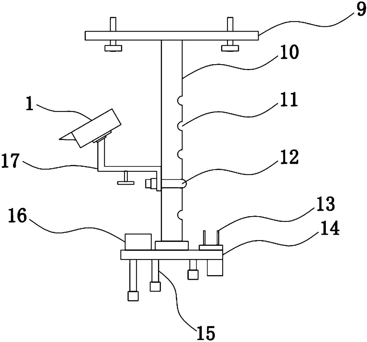
[0020] The present invention provides such Figure 1-4 Shown is a laboratory monitoring device based on the computer Internet of Things, including:

[0021] Installation column 10, the top of described installation column 10 is welded and fixed on fixed plate 9, and the bottom end of described installation column 10 is fixed with base 14 by bolt, and wireless network gateway 13, sensor assembly 15 and wireless network gateway 13, sensor assembly 15 and UPS po...


PUM


Abstract

The invention discloses a laboratory monitoring device based on the computer Internet of Things. The laboratory monitoring device comprises an installation column and an internal bracket, wherein thetop of the installation column is welded and fixed with a fixing plate; the bottom end of the installation column is fixedly provided with a base through bolts; the base is independently provided witha wireless network gateway, a sensor component and a UPS (Uninterrupted Power Supply); the top of the internal bracket is welded and fixed with the bottom of an internal thread bushing; the top end of the internal thread bushing is fixedly connected to the upper wall of an external cooling cover through bolts; the tail end of the external cooling cover is provided with a cooling fan; and a camerabody is fixed in the internal bracket. By use of the device, through the cooling fan, air motion is quickened, and a cooling fin is cooperated to improve cooling speed so as to be favorable for prolonging the service life of the camera. Through the wireless network gateway, collected data information can be sent to a monitoring terminal, and an alarm is given through the terminal when a situationis abnormal so as to prompt personnel to quickly carry out processing.

Description

technical field [0001] The invention belongs to the technical field of monitoring devices, and in particular relates to a laboratory monitoring device based on the computer Internet of Things. Background technique [0002] A typical TV monitoring system is mainly composed of five parts: front-end monitoring equipment, transmission equipment, back-end storage, control and display equipment. The back-end equipment can be further divided into central control equipment and sub-control equipment. The front-end and back-end equipment can be constructed in a variety of ways, and the connection between them (also called a transmission system) can be realized through various methods such as cables, optical fibers, and microwaves. During the operation and use of the laboratory, it is necessary to monitor the laboratory through a variety of equipment. [0003] The most direct monitoring method is the camera, through which the sudden situation in the laboratory can be monitored in time...

Claims


Application Information

Patent Timeline
IPC IPC(8): G06F11/30G08B19/00H04L29/08H04N7/18H05K7/20
CPCG06F11/3058G08B19/00H04L67/12H04N7/18H05K7/20136H05K7/20409
Inventor 王浩楠余凡石兵
Owner WUHAN UNIV OF TECH
Learn More