
Strengthened closed type medium-deep-layer buried pipe heat exchange system

A tube heat exchange and closed technology, applied in the direction of indirect heat exchangers, heat exchanger types, fixed tubular conduit components, etc., can solve the problem of small overall heat transfer, small temperature difference between supply and return water, and low heat transfer efficiency problems, to achieve the effect of ensuring stable results, preventing heat loss, and increasing heat exchange

Pending Publication Date: 2018-10-02
ZHEJIANG LUTE ENERGY TECH
View PDF1 Cites 1 Cited by
  • Summary
  • Abstract
  • Description
  • Claims
  • Application Information

AI Technical Summary

Problems solved by technology

[0004] The above structure mainly uses two S-shaped heat exchangers to improve the heat exchange efficiency of a single well. Although the heat exchange efficiency of the conventional single U-shaped and double U-shaped heat exchangers has a certain improvement, its essence is still Single-well heat exchange is adopted, so the solution still has problems such as small heat exchange area, low heat exchange efficiency, small temperature difference between supply and return water, and small overall heat exchange.

Method used


Image

  • Strengthened closed type medium-deep-layer buried pipe heat exchange system
  • Strengthened closed type medium-deep-layer buried pipe heat exchange system

Examples


Embodiment Construction

[0021] The present invention will be described in further detail below in conjunction with the accompanying drawings and specific embodiments.

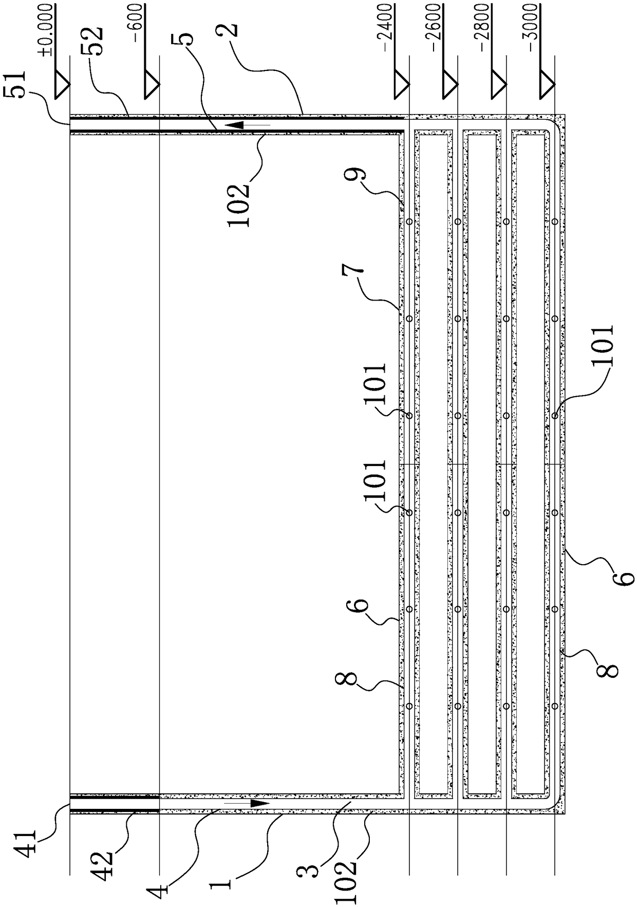
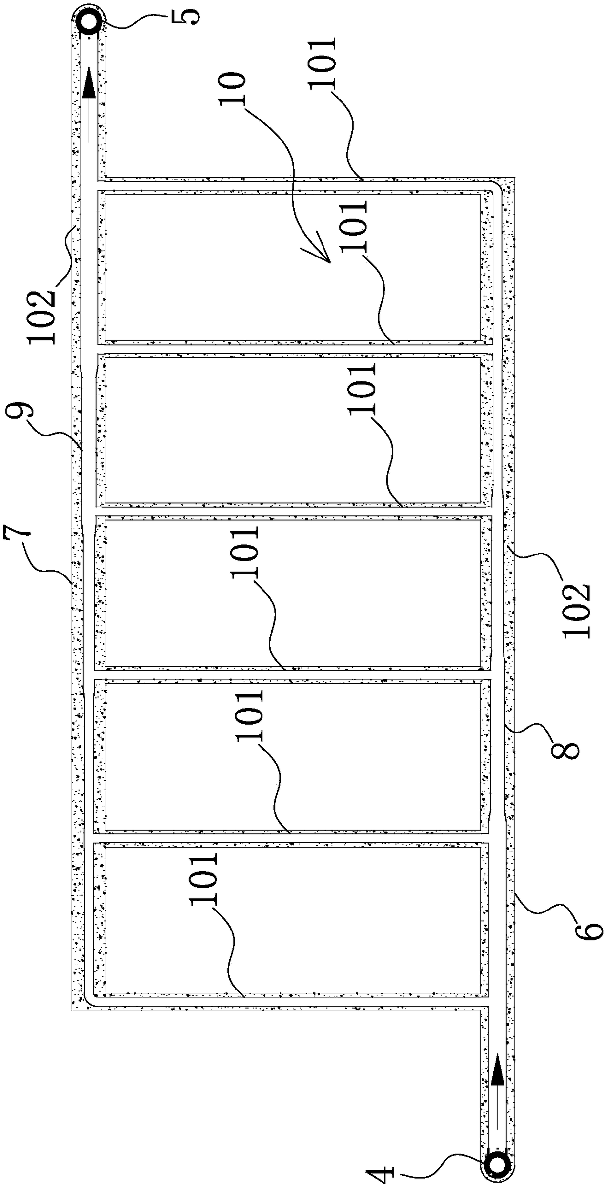
[0022] Such as Figure 1-2 As shown, the closed medium-deep buried pipe heat exchange system includes the return water shaft 1 and the water outlet shaft 2 arranged vertically and dislocated in the horizontal direction. Here, the return water shaft 1 and the water outlet shaft 2 have the same depth. Ensure that the depth is above 3,000 meters. The return vertical shaft 1 is provided with a return vertical pipe 4 with a refrigerant 3 inside. The outlet vertical shaft 2 is provided with an outlet vertical pipe 5, and the upper end of the return vertical pipe 4 is a return pipe. The water end 41, the upper end of the water outlet vertical pipe 5 is the water outlet 51, wherein, the lower end of the backwater vertical shaft 1 is sequentially provided with a number of backwater horizontal wells 6 from top to bottom, and each backwater hori...


PUM


Abstract

The invention relates to a strengthened closed type medium-deep-layer buried pipe heat exchange system. The strengthened closed type medium-deep-layer buried pipe heat exchange system solves the technical problem that existing buried pipe heat exchange efficiency is low. The strengthened closed type medium-deep-layer buried pipe heat exchange system comprises a water return vertical shaft, a wateroutlet vertical shaft, a water return vertical pipe and a water outlet vertical pipe, the upper end of the water return vertical pipe is the water return end, the upper end of the water outlet vertical pipe is the water outlet end, at least one water return horizontal shaft is arranged at the lower end of the water return vertical shaft, at least one water outlet horizontal shaft is arranged at the lower end of the water outlet vertical shaft, the water outlet horizontal shaft and the water return horizontal shaft are parallel and are arranged in a staggered manner, a water return horizontaltransverse pipe communicating the water return vertical pipe is arranged in the water return horizontal shaft in a penetrating manner, a water outlet horizontal transverse pipe communicating with thewater outlet vertical pipe is arranged in the water outlet horizontal shaft in a penetrating manner, and a branch pipe communication structure is arranged between the water return horizontal transverse pipe and the water outlet horizontal transverse pipe. The strengthened closed type medium-deep-layer buried pipe heat exchange system has the advantages that the horizontal transverse pipes and horizontal branch pipes are used for strengthening the buried pipe heat exchange area, and the system heat exchange quantity can be obviously increased. An effective heat preservation measures can be taken, and the system heat loss can be prevented.

Description

technical field [0001] The invention belongs to the technical field of geothermal energy equipment, and in particular relates to an enhanced closed medium-deep buried pipe heat exchange system. Background technique [0002] With the increasing shortage of traditional fossil energy, people's concerns about energy security and climate change are increasing day by day, and geothermal energy has also received more and more attention and recognition. In the cold northern regions, the air source and solar energy are greatly affected by the local climate environment, and the use of air source and solar energy as a heating source is extremely unstable, while geothermal energy is a green, low-carbon, inexhaustible renewable energy Gaining importance. Among them, mid-deep geothermal energy is the most valuable and potential source in the field of thermal applications, mainly referring to the thermal energy resources contained in strata 2-3km underground with a temperature of 70-90°C ...

Claims


Application Information

Patent Timeline
IPC IPC(8): F24T10/15F28D7/10
CPCF28D7/10
Inventor 危飞飞林洪宝郭丽君王清林曾迪
Owner ZHEJIANG LUTE ENERGY TECH
Learn More