
Device and method for tail gas denitrification by activated carbon method for ships

An activated carbon and denitrification technology, which is applied in the direction of exhaust devices, separation methods, and noise reduction devices, can solve the problems of high reaction temperature, large space occupation, and high economic cost, and achieve high removal efficiency, low requirements for reaction temperature, and high The effect of reaction efficiency

Active Publication Date: 2021-12-07
HARBIN ENG UNIV
View PDF11 Cites 0 Cited by
  • Summary
  • Abstract
  • Description
  • Claims
  • Application Information

AI Technical Summary

Problems solved by technology

[0007] The purpose of the present invention is to provide a tail gas denitrification device based on the activated carbon method in order to solve the defects of the original SCR technology such as large floor space, high reaction temperature and high economic cost; the present invention also provides a tail gas denitrification device based on the activated carbon method. Denitrification method

Method used


Image

  • Device and method for tail gas denitrification by activated carbon method for ships

Examples


Embodiment Construction

[0030] The present invention will be further described in detail below in conjunction with the accompanying drawings and specific embodiments.

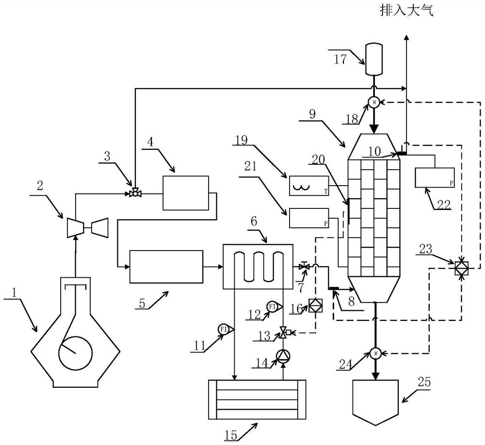
[0031] combine figure 1 : Among them, 1 is marine diesel engine, 2 is exhaust gas turbocharger, 3 is flue gas three-way valve, 4 is PM removal device, 5 is NO oxidizer, 6 is flue gas cooler, and 7 is reactor flue gas control Valve, 8 is the NOx concentration sensor at the reactor inlet, 9 is the reactor, 10 is the NOx concentration sensor at the reactor outlet, 11 is the coolant outlet flowmeter, 23 is the coolant inlet flowmeter, 13 is the electromagnetic flow control valve, 14 is Coolant supply pump, 15 is coolant storage, 16 is temperature control unit, 17 is activated carbon storage cabinet, 18 is activated carbon installation device, 19 is temperature indicator, 20 is reactor temperature sensor, 21 is flue gas inlet pressure Indicator, 22 is the flue gas outlet pressure indicator, 23 is the activated carbon delivery control unit...


PUM


Abstract

The present invention provides a tail gas denitrification device by activated carbon method for ships, which includes an exhaust gas turbocharger 2, a flue gas three-way valve 3, a PM removal device 4, a flue gas cooler 5, and also includes a NO oxidizer 5, a reactor 9, Activated carbon delivery control unit 23 and temperature control unit 16. Compared with the existing ship denitrification device, the system composition of the device is relatively simple, and the activated carbon acts as the adsorbent and the reducing agent in the present invention. Because activated carbon has strong adsorption and reduction capabilities, the size of the reactor of the denitrification system in the present invention is much smaller than that of the existing urea-based SCR denitrification system for ships. The existing ship SCR denitrification systems basically use NH3 produced from urea aqueous solution as the reducing agent. The urea aqueous solution is easy to form urea crystals on the surface of the mixer and catalyst, resulting in a decrease in the performance of the denitrification system. The consumable of the present invention is only activated carbon, which has obvious advantages.

Description

technical field [0001] The invention relates to a tail gas denitrification device and method, in particular to a ship tail gas denitrification device and method based on an activated carbon method, and belongs to the field of ship diesel engine emission control. Background technique [0002] The marine diesel engine has the advantages of high single-machine power, high fuel economy, and unit power CO 2 Low emissions and other advantages, so diesel engines are widely used in the field of marine transportation. Marine diesel engines will produce a large amount of NO in the working process. NO is a toxic air pollutant, which poses a great threat to the environment and human health. The International Maritime Organization (IMO) has always had strict restrictions on ship exhaust emissions. Among them, the Tier III emission guidelines of the MARPOL Convention were officially implemented on January 1, 2016, posing greater challenges to the NOx emission control of marine diesel eng...

Claims


Application Information

Patent Timeline
Patent Type & Authority Patents(China)
IPC IPC(8): F01N3/20F01N3/08B01D53/92B01D53/56
CPCB01D53/56B01D53/92F01N3/0807F01N3/0842F01N3/20F01N2250/12
Inventor 周松张钊朱元清冯永明
Owner HARBIN ENG UNIV
Learn More