
Electromagnetic type emergency load rejection device for underwater glider

An underwater glider, electromagnetic technology, applied to underwater ships, underwater operating equipment, motor vehicles, etc., can solve the problems of direct drive motor structure complexity, limited practicability, too many transmission links, etc., and achieve a convenient overall structure Strong control, stability and adaptability, and the effect of ensuring the safety of long-distance navigation

Active Publication Date: 2018-10-02
HUAZHONG UNIV OF SCI & TECH
View PDF5 Cites 13 Cited by
  • Summary
  • Abstract
  • Description
  • Claims
  • Application Information

AI Technical Summary

Problems solved by technology

However, further studies have shown that the above-mentioned existing solutions still have the following defects or deficiencies: First, the direct drive motor device is often complex in structure, bulky and cannot be reused, and needs to be reinstalled and debugged before each use, so the practicability is limited ;Secondly, and more importantly, the current various types of equipment fail to fully consider the matching of internal and external water pressure. Generally, dynamic seals are used. At the same time, there are problems such as complicated maintenance, too many transmission links, and insufficient reliability.

Method used


Image

  • Electromagnetic type emergency load rejection device for underwater glider
  • Electromagnetic type emergency load rejection device for underwater glider
  • Electromagnetic type emergency load rejection device for underwater glider

Examples


Embodiment Construction

[0022] In order to make the object, technical solution and advantages of the present invention clearer, the present invention will be further described in detail below in conjunction with the accompanying drawings and embodiments. It should be understood that the specific embodiments described here are only used to explain the present invention, not to limit the present invention. In addition, the technical features involved in the various embodiments of the present invention described below can be combined with each other as long as they do not constitute a conflict with each other.

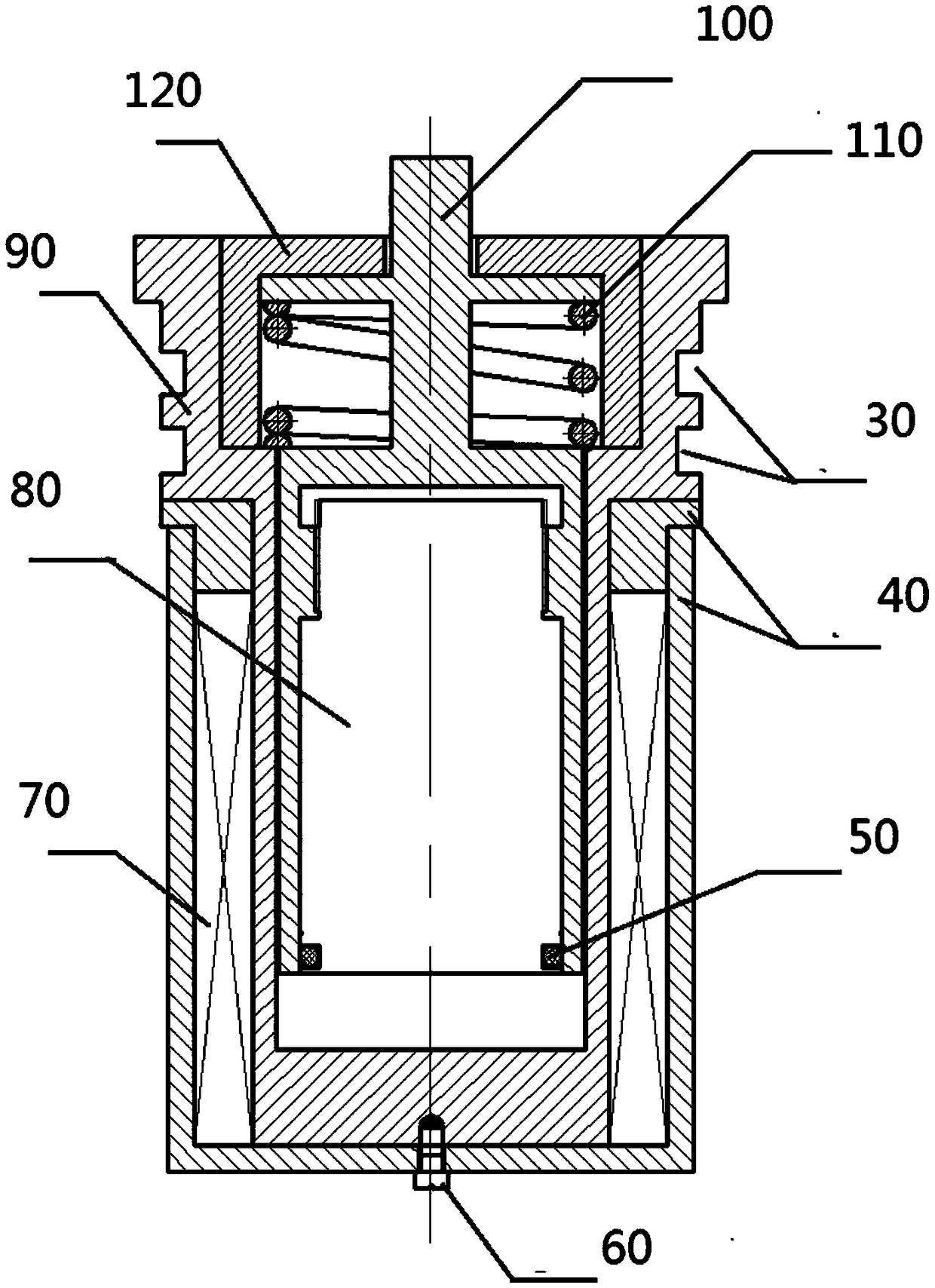
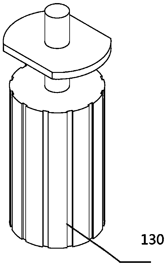
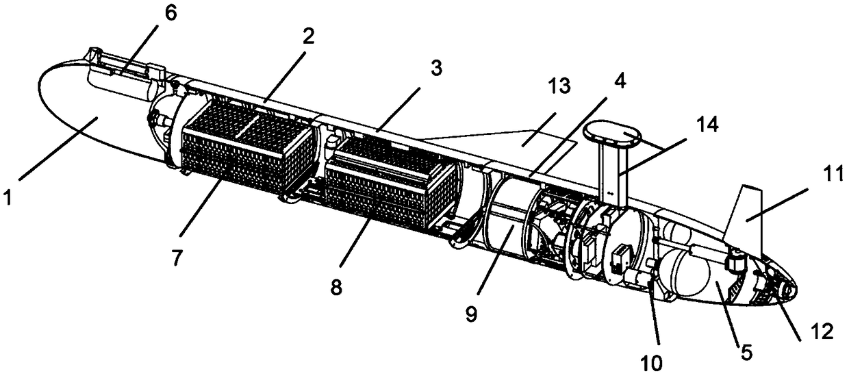
[0023] figure 1 It is a sectional view of the overall structure of the electromagnetic emergency dumping device constructed according to the present invention. Such as figure 1 As shown, the electromagnetic emergency dumping device is mainly designed for equipment such as underwater glider, and it can be sealed and installed in the stern motor cabin of the underwater glider, for example, and i...


PUM


Abstract

The invention belongs to the technical field of underwater vehicle related parts, and discloses an electromagnetic type emergency load rejection device for an underwater glider. The electromagnetic type emergency load rejection device comprises a mounting base, a stainless steel shaft, an iron core, an electromagnetic winding and a steel casing. The iron core is arranged in the lower end of the stainless steel shaft in an embedded mode, and then integrally installed in a groove cavity of the mounting base in a sleeved mode together with the stainless steel shaft, and the upper end of the stainless steel shaft is sealed by a sealing cover and a compression spring. In addition, an electromagnet element is formed in the formed sealed space, and the iron core is driven to move up and down in real time and efficiently through electromagnetic induction when energized, so that the stainless steel shaft is driven to be removed from the mounting base to enable a load rejection block on the stainless steel shaft to be released in an emergency. Through the electromagnetic type emergency load rejection device for the underwater glider, the straight driving principle and the internal and external pressure balancing mechanism can be utilized comprehensively, the constant load rejection driving force can be obtained under the premise of significantly reducing the transmission link, and at thesame time, the characteristics of no need for dynamic seal, easy operation and control, low maintenance complexity and high reliability are achieved.

Description

technical field [0001] The invention belongs to the technical field of accessories related to underwater vehicles, and more specifically relates to an electromagnetic emergency dumping device for an underwater glider. Background technique [0002] With the deepening of ocean exploration, the application of underwater vehicles is becoming more and more extensive. There are two main types of underwater vehicles currently in use. One is the traditional underwater vehicle propelled by a propeller, and the speed is generally 3-5kn. , but the voyage and voyage time are limited; the other is the underwater glider that has been booming in recent years, which can obtain a speed of about 0.5kn through the change of the ratio of buoyancy to gravity and the attitude angle, and has a long range and voyage Time has been greatly improved. [0003] Facing the complex environmental conditions of ocean exploration, when various emergencies occur in the underwater glider, it is usually necess...

Claims


Application Information

Patent Timeline
IPC IPC(8): B63C11/52B63G8/14
CPCB63C11/52B63G8/14
Inventor 杨钢张建星李宝仁高隆隆傅晓云杜经民雷磊高磊金培训邹达明付俊杰
Owner HUAZHONG UNIV OF SCI & TECH
Learn More