
Vacuum drop-out-type switch

A technology of drop switch and vacuum switch, which is applied in the direction of electric switch, high voltage/high current switch, high voltage air circuit breaker, etc. It can solve the problems of high labor cost, delay of power supply restoration, maintenance and closing operation difficulties, etc.

Pending Publication Date: 2018-09-28
JILIN GUHETAI MACHINERY
View PDF0 Cites 3 Cited by
  • Summary
  • Abstract
  • Description
  • Claims
  • Application Information

AI Technical Summary

Problems solved by technology

[0002] At present, the short-circuit tripping of the line is performed by manual inspection. After the fault is eliminated, it also needs to be closed manually. Instantaneous, because the passage of high current will burn out foreign objects or shoot down birds, so that the short-circuit fault caused by the above reasons will disappear immediately. In this case, there will be no problem as long as the switch is reclosed. It is not a permanent fault, but the traditional fuse drop The switch must be replaced by the staff on site, and the power supply can be restored by manual closing. Due to the dense network of power transmission and distribution lines in our country, it is very labor-intensive and time-consuming to inspect and inspect the line when the line fails. It is even more difficult to maintain and close the lines erected in high mountains or in uninhabited areas; it leads to delays in restoring power supply, high labor costs, and it is difficult to find the accident point

Method used


Image

  • Vacuum drop-out-type switch
  • Vacuum drop-out-type switch
  • Vacuum drop-out-type switch

Examples


Embodiment Construction

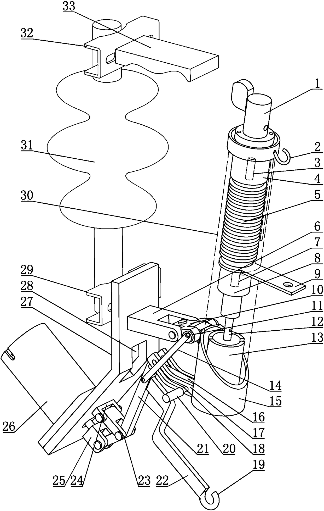
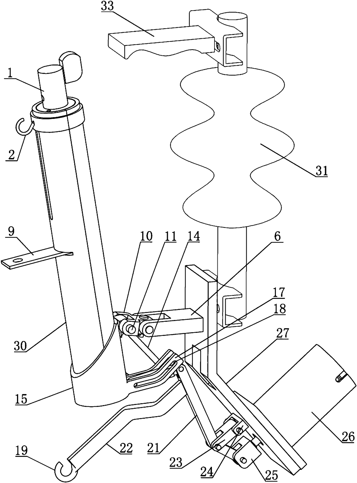
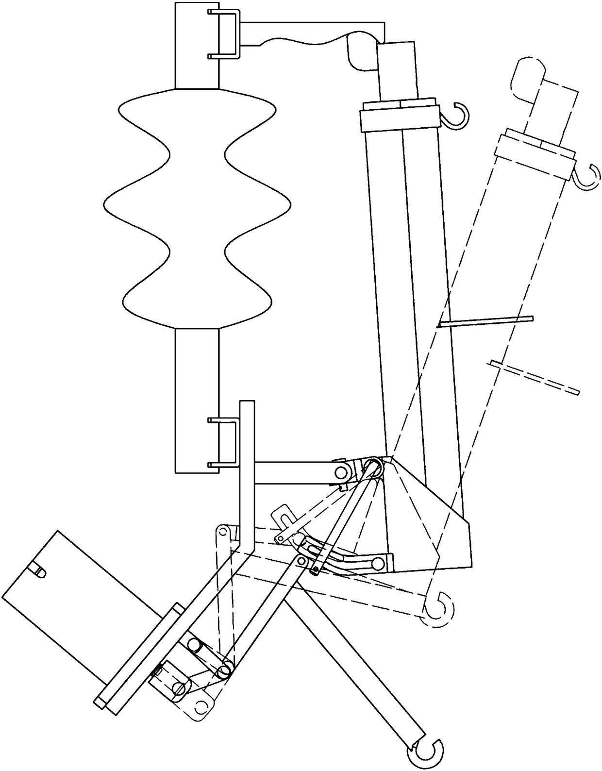
[0015] The vacuum drop switch has a drop action mechanism and a vacuum switch assembly. The drop action mechanism has a bracket 27, a first hinge seat 6, a second hinge seat 24, a crank arm 21, a first permanent magnet action mechanism 26, a base 15, a first The hinge seat, the second hinge seat, and the first permanent magnet action mechanism are installed on the bracket, and the first hinge seat is equipped with a first connecting plate 10, one end of the first connecting plate is hinged with the first hinge seat, and the other end is hinged with the upper part of the base The second hinge base is equipped with a second connecting plate 23, one end of the second connecting plate is hinged with the second hinge base, the other end is hinged with the middle part of the crank arm, and one end of the crank arm is hinged with the drive rod 25 of the first permanent magnet action mechanism , the other end of the crank arm is connected to the lower part of the base through a hinge. ...


PUM


Abstract

The invention discloses a vacuum drop-out-type switch. A drop-out action mechanism of the vacuum drop-out-type switch comprises a support frame, a first hinge base, a second hinge base, a crank arm, afirst permanent magnet action mechanism and a base. The first hinge base, the second hinge base and the first permanent magnet action mechanism are mounted on the support frame. A first connection plate is mounted on the first hinge base. One end of the first connection plate is hinged with the first hinge base, and the other end of the first connection plate is hinged with the upper portion of the base. A second connection plate is mounted on the second hinge base. One end of the second connection plate is hinged with the second hinge base, and the other end of the second connection plate ishinged with the middle of the crank arm. One end of the crank arm is hinged with a driving rod of the first permanent magnet action mechanism. The other end of the crank arm is connected with the lower portion of the base. The lower end of a tube of a vacuum switch component is fixedly connected with the base. A main connection terminal is arranged at the top end of the tube. An outgoing-line terminal is arranged in the middle or on the lower portion of the tube. A vacuum envelope, an insulating body and a second permanent magnet action mechanism are arranged in the tube from top to bottom. The vacuum drop-out-type switch has the advantages that power restoration can be realized in case of transient faults, a separating brake can drop out in case of non-transient faults, accident points are easy to judge, and remote closing operation can be realized.

Description

technical field [0001] The invention discloses a vacuum drop switch, which belongs to the field of transmission line protection devices. Background technique [0002] At present, the short-circuit tripping of the line is performed by manual inspection. After the fault is eliminated, it also needs to be closed manually. Instantaneous, because the passage of high current will burn out foreign objects or shoot down birds, so that the short-circuit fault caused by the above reasons will disappear immediately. In this case, there will be no problem as long as the switch is reclosed. It is not a permanent fault, but the traditional fuse drop The switch must be replaced by the staff on site, and the power supply can be restored by manual closing. Due to the dense network of power transmission and distribution lines in our country, it is very labor-intensive and time-consuming to inspect and inspect the line when the line fails. It is even more difficult to maintain and close the l...

Claims


Application Information

Patent Timeline
IPC IPC(8): H01H33/664H01H33/666H01H33/38H01H33/42H01H85/54
CPCH01H33/38H01H33/42H01H33/664H01H33/666H01H85/54
Inventor 布有刚薛亮
Owner JILIN GUHETAI MACHINERY
Learn More