
Quantitative-rotating winding machine mount for winding dry transformer high-voltage coil

A technology for dry-type transformers and high-voltage coils, which is applied in inductance/transformer/magnet manufacturing, coil manufacturing, electrical components, etc. Effect

Active Publication Date: 2018-09-28
TAIZHOU GENTECK ELECTRIC
View PDF5 Cites 1 Cited by
  • Summary
  • Abstract
  • Description
  • Claims
  • Application Information

AI Technical Summary

Problems solved by technology

[0003] Nowadays, the general dry-type transformers are made by high and low voltage separate winding, and the high-voltage coils are mostly made by wire winding. When high-voltage coils are wound, most of them need to be wound in sections, so that It is necessary to reverse the direction of the coil when the coil is wound. Since most of the winding machines are fixed on the ground now, workers need to lift the coil from the winding machine after winding part of the coil and turn it around. Coil direction, and then install the coil back on the winding machine, such an operation is not only troublesome, but also has certain safety hazards. Based on the above problems, we have made continuous improvements and proposed a quantitative rotation dry-type transformer high-voltage coil winding. Machine base

Method used


Image

  • Quantitative-rotating winding machine mount for winding dry transformer high-voltage coil
  • Quantitative-rotating winding machine mount for winding dry transformer high-voltage coil
  • Quantitative-rotating winding machine mount for winding dry transformer high-voltage coil

Examples


Embodiment Construction

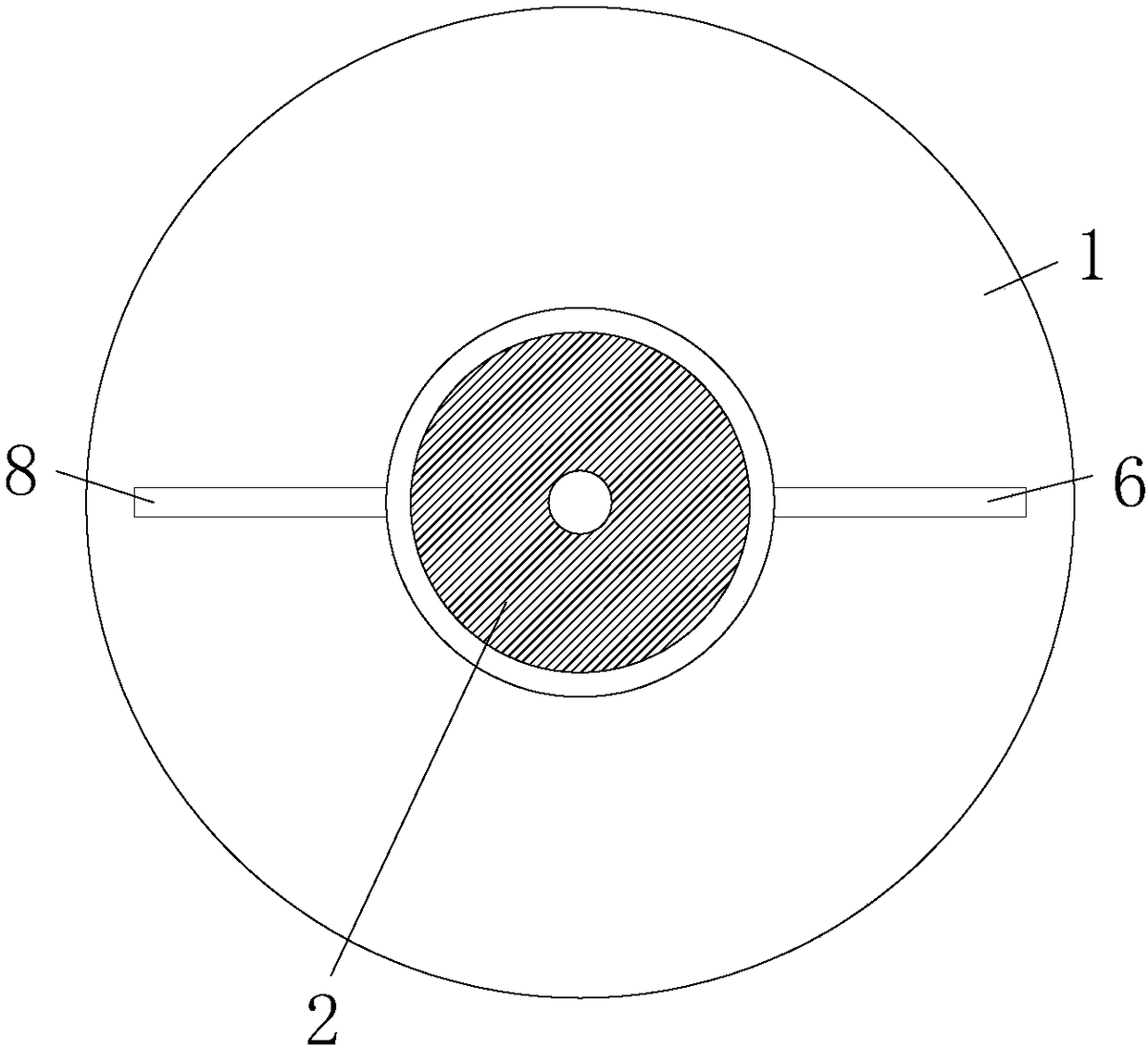
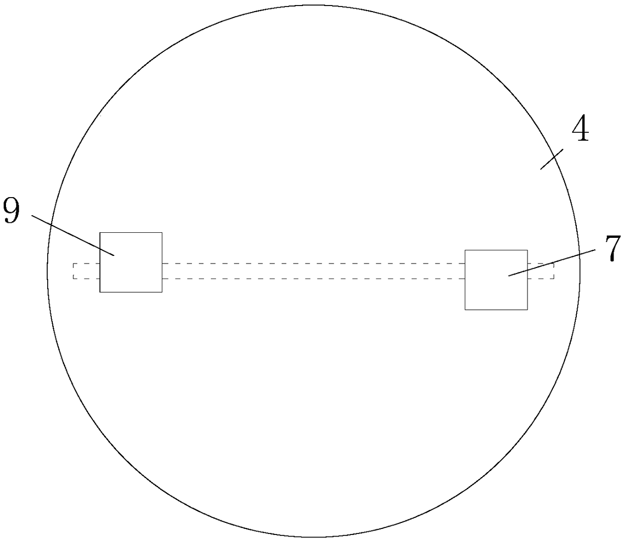
[0030] like Figure 1-9As shown, the present invention provides a technical solution: a winding machine base for quantitatively rotating dry-type transformer high-voltage coil winding, including a fixed circular plate 1, which is fixed in a groove opened on the ground, The central position of the fixed circular plate 1 is vertically connected with a conical rotary positioning seat 2, the inner wall of the conical rotary positioning seat 2 is socketed with the outer surface of the conical positioning rotary block 3, and the top of the conical positioning rotary block 3 is in contact with the rotating circle. The center position of the bottom of the plate 4 is fixedly connected, the top of the rotating circular plate 4 is fixedly connected with the bottom of the winding machine body 5, and the conical rotating positioning seat 2 fixedly connected to the top of the fixed circular plate 1 and the bottom of the rotating circular plate 4 are fixed. Connected conical positioning and ...


PUM


Abstract

The invention relates to the technical field of the transformer manufacture equipment, and especially relates to a quantitative-rotating winding machine mount for winding a dry transformer high-voltage coil. The quantitative-rotating winding machine mount comprises a fixed circular plate, a conical rotary positioning seat is vertically connected to the center location of the fixed circular plate,the inner wall of the conical rotary positioning seat is sleeved on the outer surface of a conical positioning rotary block, the top of the conical positioning rotary block is fixedly connected with the center location of the bottom of a swirling circular plate, the top of the swirling circuit plate is fixedly connected with the bottom of the winding machine body, and the right side of the conicalrotary positioning seat is fixedly connected with one end of a first cylinder stop lever. Through the quantitative-rotating winding machine mount for winding the dry transformer high-voltage coil, the stability of the swirling circular plate in the rotary process is excellent through the conical rotary positioning seat fixedly connected with the top of the fixed circular plate and the conical positioning rotary block fixedly connected with the bottom of the swirling circuit plate; and the winding machine mount disclosed by the invention is more suitable for the U-turn of the winding machine in comparison with the traditional rotary mechanism.

Description

technical field [0001] The invention relates to the technical field of transformer manufacturing equipment, in particular to a winding machine base for quantitatively rotating high-voltage coils of dry-type transformers. Background technique [0002] The transformer is a device that can change the AC voltage made by the principle of electromagnetic induction. It is composed of a high-voltage coil, a low-voltage coil and an iron core. The power transformer is an indispensable and important device in the process of power transmission. With the advantages of explosion, no pollution and avoidable fire, it has been widely used in various types of substation places; [0003] Nowadays, the general dry-type transformers are made by high and low voltage separate winding, and the high-voltage coils are mostly made by wire winding. When high-voltage coils are wound, most of them need to be wound in sections, so that It is necessary to reverse the direction of the coil when the coil is...

Claims


Application Information

Patent Timeline
Patent Type & Authority Applications(China)
IPC IPC(8): H01F41/06H01F41/082
CPCH01F41/06H05K5/0234
Inventor 汪辉
Owner TAIZHOU GENTECK ELECTRIC
Learn More