
Magnetic force strengthening and steering component

A component and magnetic technology, applied in the field of permanent magnet unit products, can solve the problems of maintenance, use doubts, and the use of electromagnetics is not worthwhile, and achieves the effect of simple manufacturing and easy mass production.

Pending Publication Date: 2018-09-28
NANJING MAGNESTER ENVIRONMENTAL PROTECTION SCI & TECH LTD
View PDF0 Cites 1 Cited by
  • Summary
  • Abstract
  • Description
  • Claims
  • Application Information

AI Technical Summary

Problems solved by technology

[0002] The application of magnetic science and technology has a history of more than 60 years. The magnetic source is divided into electromagnetic and permanent magnet. In the past, the magnetic induction intensity of permanent magnet was small, and the surface magnetism was only more than 2000 Gauss. The equipment has shortcomings such as large investment, power consumption, maintenance, and accidents, so there are many doubts about its use
[0003] Since Japan developed NdFeB series magnets with very high magnetic field strength for commercial application more than 20 years ago, the magnetic induction intensity has reached more than 5000 gauss, which can replace permanent magnets in this part of the application, but about 10000 gauss The application space is very large, and it is not worthwhile to use electromagnetism, so it is extremely necessary to develop permanent magnet products with a surface magnetism of 10,000 Gauss or more

Method used


Image

  • Magnetic force strengthening and steering component

Examples


Embodiment Construction

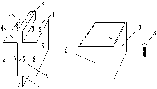
[0017] attached figure 1 Non-restrictive disclosure of the specific structure of the embodiments of the present invention, the following in conjunction with the attached figure 1 The present invention is further described.

[0018] Such as figure 1 As shown, the main body of the present invention includes a rectangular three-dimensional magnet 1 ; a magnetizer 2 ; and a stainless steel shell 3 .

[0019] In the present embodiment: the rectangular three-dimensional magnet 1 is magnetized on the largest surface, and one side is an N pole and the other side is an S pole. The magnetizer 2 is a rectangular thick sheet-like three-dimensional, and its height is higher than that of the three-dimensional magnet 1. There are shallow grooves 4 at both sides of the waist, and there are magnetic assembly holes 5 in the center of the front and rear sides. The front and rear sides of the stainless steel shell 3 have a shell assembly hole 6 in the center, and its size and position are cons...


PUM


Abstract

The invention mainly utilizes a principle that the magnetic induction intensity represents the number of magnetic force lines passing through a unit area vertically, and enhances the magnetic induction intensity on the basis of reducing a magnetic flux area without changing the number of the magnetic force lines. According to the scheme of the invention, the same magnetic poles of two magnets arerelatively squeezed to a small distance, so that the original magnetic flux area is reduced, and the magnetic induction intensity is enhanced; and then a special magnetizer is sandwiched between the two magnets, so that the magnetic force lines are deflected along with the magnetizer and diverged from a protruding part of the magnetizer, at this time, not only the magnetic induction intensity is enhanced, but also the magnetic force acting direction is changed by 90 degrees, and the size and shape of the protruding part of the magnetizer can be designed as required; and finally, a stainless steel housing is arranged to perform protection and fixation. The product of the invention can be used as a magnetic component unit for designing other magnetic products.

Description

technical field [0001] The invention relates to a component for strengthening magnetic force and turning, in particular to developing a permanent magnet unit product with strong magnetic force. Background technique [0002] The application of magnetic science and technology has a history of more than 60 years. The magnetic source is divided into electromagnetic and permanent magnet. In the past, the magnetic induction intensity of permanent magnet was small, and the surface magnetism was only more than 2000 Gauss. The equipment has shortcomings such as large investment, power consumption, maintenance, and accidents, so there are many doubts about its use. [0003] Since Japan developed NdFeB series magnets with very high magnetic field strength for commercial application more than 20 years ago, the magnetic induction intensity has reached more than 5000 gauss, which can replace permanent magnets in this part of the application, but about 10000 gauss The application space is...

Claims


Application Information

Patent Timeline
Patent Type & Authority Applications(China)
IPC IPC(8): H01F7/02
CPCH01F7/021
Inventor 高明雄
Owner NANJING MAGNESTER ENVIRONMENTAL PROTECTION SCI & TECH LTD
Learn More