GIS loop resistance testing device and method without removing grounding rows

A technology of loop resistance and testing equipment, which is applied in the direction of measuring equipment, measuring resistance/reactance/impedance, measuring electrical variables, etc. It can solve the problems of threatening the personal safety of operators, affecting the efficiency of on-site work, and consuming time and effort for grounding bars, etc., to achieve Simplify the operation process, eliminate the risk of induction electric injury, and improve work efficiency

Pending Publication Date: 2018-09-28
ZHONGSHAN POWER SUPPLY BUREAU OF GUANGDONG POWER GRID
View PDF0 Cites 5 Cited by
  • Summary
  • Abstract
  • Description
  • Claims
  • Application Information

AI Technical Summary

Problems solved by technology

With the improvement of power supply reliability requirements, the tested equipment is generally in a single-interval power outage state, that is to say, the equipment around the workplace is generally live, especially the GIS equipment with a voltage level of 220kV and above. The equipment grounding switch is in a strong electric field. When the grounding bar is removed, the induced voltage is very high. In this state, the test wiring will seriously threaten the personal safety of the operators.
In addition, it is time-consuming and laborious to disassemble and assemble the ground bar before and after the test, which seriously affects the work efficiency on site

Method used


Image

  • GIS loop resistance testing device and method without removing grounding rows
  • GIS loop resistance testing device and method without removing grounding rows

Examples


Embodiment 1

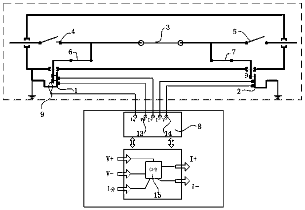
[0027] Such as figure 1Shown is the first embodiment of the GIS loop resistance testing device and method without removing the grounding bar of the present invention. The GIS loop is located inside the GIS equipment shell, including the first grounding bar 1, the second grounding bar 2, the GIS switch 3, The first knife switch 4 and the second knife switch 5, the first knife switch 4, the GIS switch 3, and the second knife switch 5 are connected in series to form a GIS main circuit, and the first grounding bar 1 is connected in parallel to the first Between the knife switch 4 and the GIS switch 3, the second ground bar 1 is connected in parallel between the second knife switch 5 and the GIS switch 3; the first ground bar 1, the second ground bar 2 and the GIS main The first grounding knife switch 6 and the second grounding knife switch 7 are respectively connected between the loops, and a parallel shunt is formed between the first grounding bar 1, the second grounding bar 2 an...

Embodiment 2

[0036] Such as figure 2 Shown is the second embodiment of the GIS loop resistance testing device and method without dismantling the grounding bar of the present invention. This embodiment is similar to the first embodiment, the difference is that the first grounding bar 1, the second The ground bars 2 each include a phase A ground bar, a B phase ground bar, and a C phase ground bar, and the A phase ground bar, the B phase ground bar, and the C phase ground bar are connected in series through copper pieces 10, so The copper part 10 is grounded; the Hall element 9 includes a first Hall element 11 and a second Hall element 12, and the first Hall element 11 is arranged between the A-phase ground row and the B-phase ground row The second Hall element 12 is arranged on the copper piece 10 between the B-phase ground bar and the C-phase ground bar.

[0037] When testing the B-phase loop resistance, the specific implementation of the present embodiment is as follows:

[0038] S1. Di...


PUM


Abstract

The invention relates to the technical field of a GIS switch loop resistance testing device and particularly relates to a GIS loop resistance testing device and method without removing grounding rows.The testing device comprises a loop resistance tester and a Hall element used for testing a shunt value of a parallel branch, wherein the loop resistance tester is connected between the first grounding row and the second grounding row, the Hall element is arranged on the parallel branch, and an output end of the Hall element is connected with an input end of the loop resistance tester. The testing device is advantaged in that when an actual value of the GIS loop resistance is measured, removing the grounding rows on both sides is not needed, the inductive electric injury risk caused by disassembling the grounding rows can be eliminated, the operational flow of the GIS loop resistance test is simplified, work efficiency of the field can be improved, moreover, the Hall element is utilized to test the shunt value of the parallel branch instead of removing the grounding rows to eliminate shunt influence of the parallel branch, raw materials are readily available, the device is simple, andrelatively good practicality is realized.

Description

technical field [0001] The invention relates to the technical field of a GIS switch loop resistance test device, and more specifically, relates to a GIS loop resistance test device and method without dismantling the grounding bar. Background technique [0002] The GIS switch circuit resistance test is to conduct a pressure test on the grounding copper bars of the grounding switches on both sides of the switch. Generally, it is measured by applying a test current to the external grounding bars of the grounding bars on both sides of the circuit under test, but the grounding bars on both sides It will form two parallel branches with the grounding grid and the GIS shell to generate a shunt and affect the measurement results. The current test method needs to remove one side of the grounding bars on both sides, and the loop resistance of the GIS switch can be accurately measured only under the condition of eliminating the parallel branch. With the improvement of power supply reli...

Claims


Application Information

Patent Timeline
IPC IPC(8): G01R27/08
CPCG01R27/08
Inventor 王凯陈权王伟平
Owner ZHONGSHAN POWER SUPPLY BUREAU OF GUANGDONG POWER GRID
Why Eureka
Try Eureka