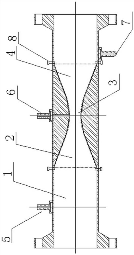
Venturi tube flow measuring device and installation method
A Venturi tube and flow measurement technology, applied in the direction of volume/mass flow generated by mechanical effects, and the detection of fluid flow by measuring differential pressure, which can solve the problems of high manufacturing cost, complex process, fluid leakage, etc., and reduce production costs. , The effect of reducing processing difficulty and reducing pressure loss
- Summary
- Abstract
- Description
- Claims
- Application Information
AI Technical Summary
Problems solved by technology
Method used
Image
Examples
Embodiment 1
[0020] A Venturi tube flow measurement device, the flow measurement device includes an inlet cylinder section 1, a conical constriction section 2, a cylinder throat section 3 and a conical divergence section 4 arranged in sequence, on the inlet cylinder section 1 along There are positive pressure-taking holes 5 in the radial direction, and negative pressure-taking ports 6 are arranged in the radial direction in the cylindrical throat section 3, and the conical constriction section 2 of the Venturi tube, the cylindrical throat section 3 and the conical diffuser section 4 are integrated Molded castings, the outer diameters of the two ports of the conical constriction section 2 and the conical diffusion section 4 of the Venturi tube are adapted to the inner diameter of the inlet cylindrical section 1; the conical constriction section 2 of the Venturi tube and the cylindrical throat section 3 The cross-section of the conical diverging section 4 is a hyperbola, and the two ends of t...
Embodiment 2
[0023] A Venturi tube flow measurement device, the flow measurement device includes an inlet cylinder section 1, a conical constriction section 2, a cylinder throat section 3 and a conical divergence section 4 arranged in sequence, on the inlet cylinder section 1 along There are positive pressure-taking holes 5 in the radial direction, and negative pressure-taking ports 6 are arranged in the radial direction in the cylindrical throat section 3, and the conical constriction section 2 of the Venturi tube, the cylindrical throat section 3 and the conical diffuser section 4 are integrated Injection molded parts, the outer diameters of the two ports of the conical constriction section 2 and the conical diffusion section 4 of the Venturi tube are adapted to the inner diameter of the inlet cylindrical section 1; the conical constriction section 2 of the Venturi tube, the cylindrical throat section 3 and the conical diffuser section 4 are hyperbolic in section, and the two ends of the ...
Embodiment 3
[0026] A Venturi tube flow measurement device, the flow measurement device includes an inlet cylinder section 1, a conical constriction section 2, a cylinder throat section 3 and a conical divergence section 4 arranged in sequence, on the inlet cylinder section 1 along There are positive pressure-taking holes 5 in the radial direction, and negative pressure-taking ports 6 are arranged in the radial direction in the cylindrical throat section 3, and the conical constriction section 2 of the Venturi tube, the cylindrical throat section 3 and the conical diffuser section 4 are integrated Injection molded parts, the outer diameters of the two ports of the conical constriction section 2 and the conical diffusion section 4 of the Venturi tube are adapted to the inner diameter of the inlet cylindrical section 1; the conical constriction section 2 of the Venturi tube, the cylindrical throat section 3 and the conical diffuser section 4 are hyperbolic in section, and the integrated casti...
PUM
 Abstract
Description
Claims
Application Information
 - R&D
- Intellectual Property
- Life Sciences
- Materials
- Tech Scout
- Unparalleled Data Quality
- Higher Quality Content
- 60% Fewer Hallucinations
Browse by: Latest US Patents, China's latest patents, Technical Efficacy Thesaurus, Application Domain, Technology Topic, Popular Technical Reports.
© 2025 PatSnap. All rights reserved.Legal|Privacy policy|Modern Slavery Act Transparency Statement|Sitemap|About US| Contact US: help@patsnap.com

