
Nuclear environment wall lamp

A technology for environment and wall lamps, applied in lighting devices, cooling/heating devices of lighting devices, light sources, etc., can solve problems such as high heat generation, high power consumption, and insufficient brightness, and achieve long life, uniform and soft light, and luminous big angle effect

Pending Publication Date: 2018-09-28
WAROM TECH INC
View PDF0 Cites 1 Cited by
  • Summary
  • Abstract
  • Description
  • Claims
  • Application Information

AI Technical Summary

Benefits of technology

This technology allows for easy maintenance or upgrading of lights without requiring them be shut down completely during use. It also provides efficient cooling while maintaining good quality colors over time. Additionally it uses LEDs that produce white brightness but have shorter lifespan than traditional bulbs due to their small size. Overall this makes these technologies more durably effective at producing consistently shiny colored lights on large areas like streets.

Problems solved by technology

The technical problem addressed by this patented inventor relates to developing new types of fluorescence bulbs that provide better energy efficiency while also having longer life spans without requiring expensive maintenance or specialized equipment. This would be useful because existing sources like glow plugs may become obsolete over time due to their limited lifetime.

Method used


Image

  • Nuclear environment wall lamp
  • Nuclear environment wall lamp
  • Nuclear environment wall lamp

Examples


Embodiment Construction

[0042] Below in conjunction with accompanying drawing and embodiment the present invention will be further described:

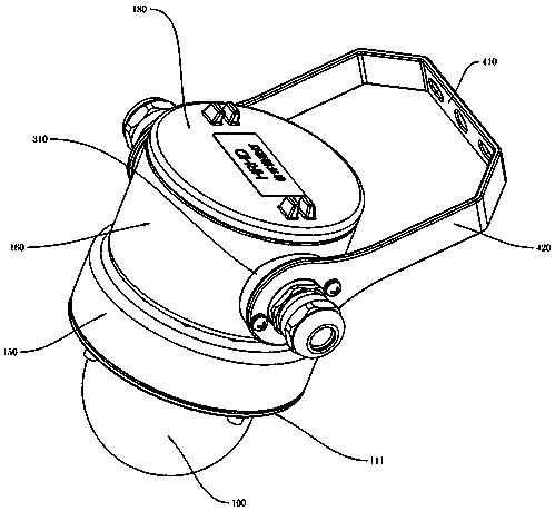
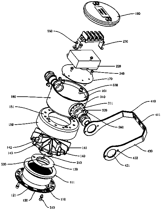
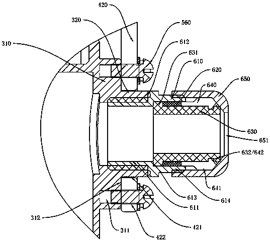
[0043] see Figure 1-Figure 7 , a nuclear environment wall lamp, comprising: a lampshade 110, the end of the lampshade 110 is provided with a clamping ring 111, and the clamping ring 111 is installed in the heat dissipation installation groove 144 of the radiator 140 and connected with the reflector 130 The closed end of the heat dissipation installation groove 144 is pressed tightly, and the end surface of the reflector 130 facing the lampshade is provided with a reflective coating, which can reflect light to the lampshade 110;

[0044] The reflective mirror 130 is provided with a reflective installation hole 131, the light source board 210 is installed in the reflective installation hole 131 and the second screw 520 is assembled and fixed with the radiator 140 after passing through the light source board 210, so that the light source board 210 is fixed on t...


PUM


Abstract

The invention discloses a nuclear environment wall lamp. The nuclear environment wall lamp comprises a lampshade. The end portion of the lampshade is provided with a clamping ring. The clamping ring is put into a heat dissipation installing groove of a heat dissipation device and is tightly pressed to the closed end of the heat dissipation installing groove through a reflector. The reflector is provided with a light reflecting installation hole, a light source plate is put into the light reflecting installation hole, after penetrating the light source plate, second screws are assembled and fixed to the heat dissipation device so that the light source plate can be fixed to the heat dissipation device, and the light source plate is provided with a light source. The outer side of the clampingring is tightly pressed into the heat dissipation installing groove through a pressing ring, and the pressing ring is assembled and fixed to a heat dissipation body on the heat dissipation device through first screws so that the pressing ring can compress the clamping ring. The pressing ring is provided with first through holes. The heat dissipation device is put into a first inner cavity of a first outer shell, and the closed end of the first outer shell is provided with a plurality of second through holes. After penetrating a second outer shell, third screws are assembled and fixed to heatdissipation installing columns so that the second outer shell, the first outer shell and the heat dissipation device can be assembled into a whole.

Description


Claims


Application Information

Patent Timeline
Owner WAROM TECH INC
Learn More