Emulsification treatment equipment for medium viscous crude oil viscosity reduction
A technology for emulsification treatment and crude oil, which is applied in the direction of production fluid, wellbore/well components, earthwork drilling and production, etc. It can solve the problems of inability to realize remixing, control the input of viscosity reducer, etc., and achieve the reduction of inclination angle and flow reduction Resistance, the effect of increasing the return ratio
- Summary
- Abstract
- Description
- Claims
- Application Information
AI Technical Summary
Problems solved by technology
Method used
Image

Examples
specific Embodiment approach 1
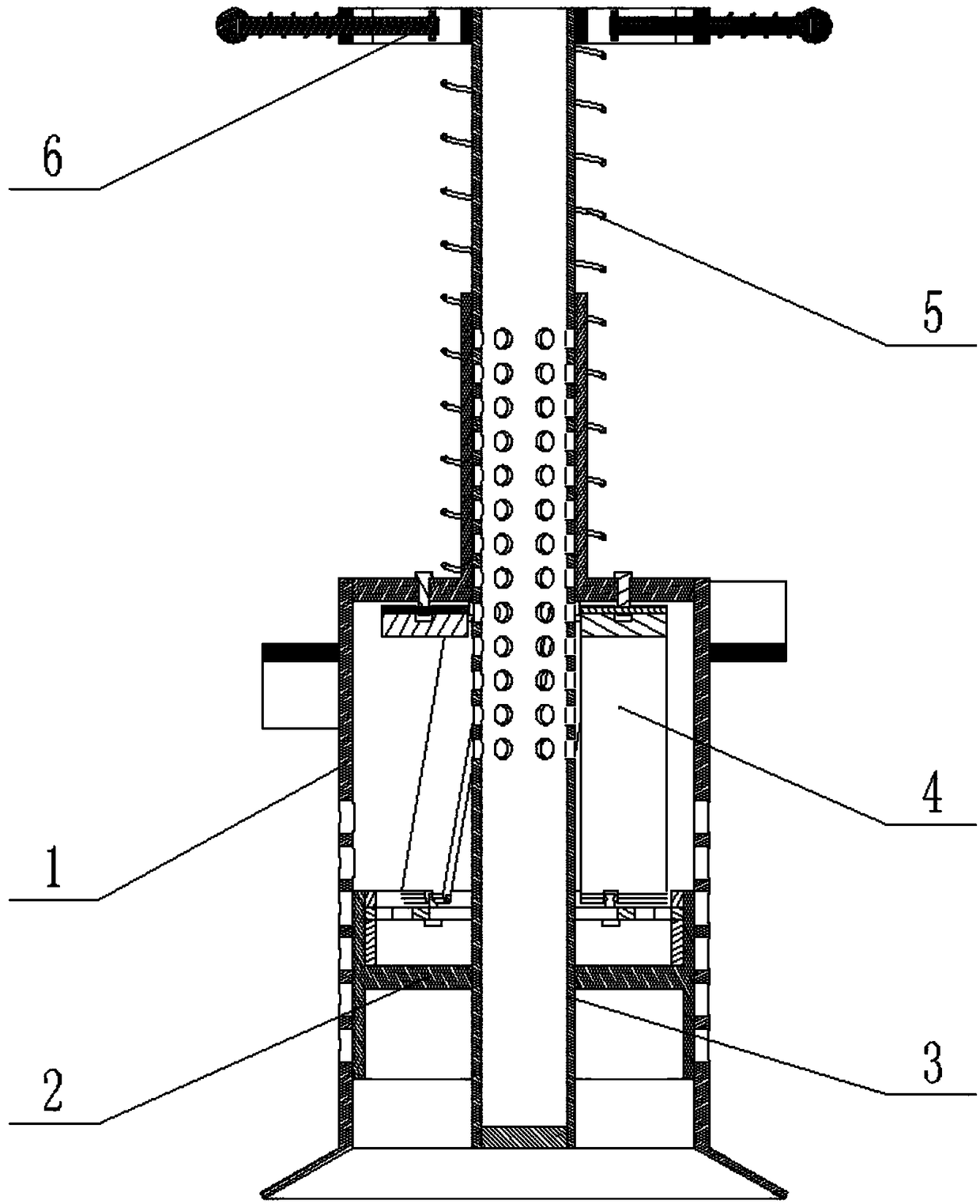
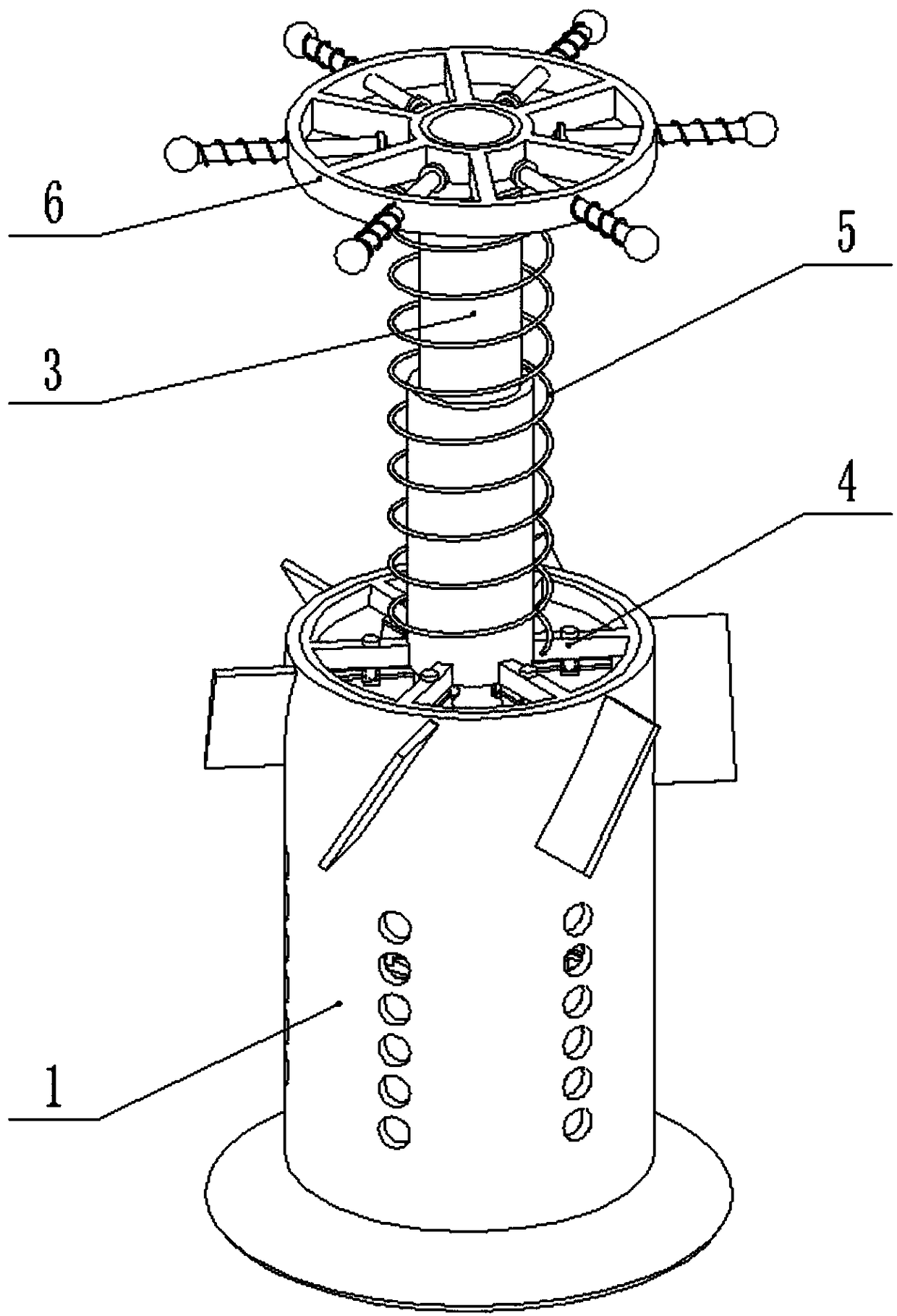
[0030] Combine below Figure 1-10 Description of this embodiment, viscous crude oil viscosity reduction emulsification treatment equipment, including stirring sleeve 1, oil sealing sleeve 2, viscosity reducing agent delivery pipe 3, internal rotation assembly 4, spring 5 and fixing device 6, the oil sealing sleeve 2 Slidingly connected in the stirring sleeve 1, the oil sealing sleeve 2 is fixedly connected to the viscosity reducing agent delivery pipe 3, the lower end of the internal rotation assembly 4 is connected to the oil sealing sleeve 2 in rotation, the middle of the internal rotation assembly 4 The end is fixedly connected to the stirring sleeve 1, the internal rotation assembly 4 is slidably connected to the viscosity reducer delivery pipe 3, the fixing device 6 is fixedly connected to the upper end of the viscosity reducer delivery pipe 3, and the spring 5 is set inside Between the screw assembly 4 and the fixing device 6; when in use, the viscous crude oil viscosity...
specific Embodiment approach 2
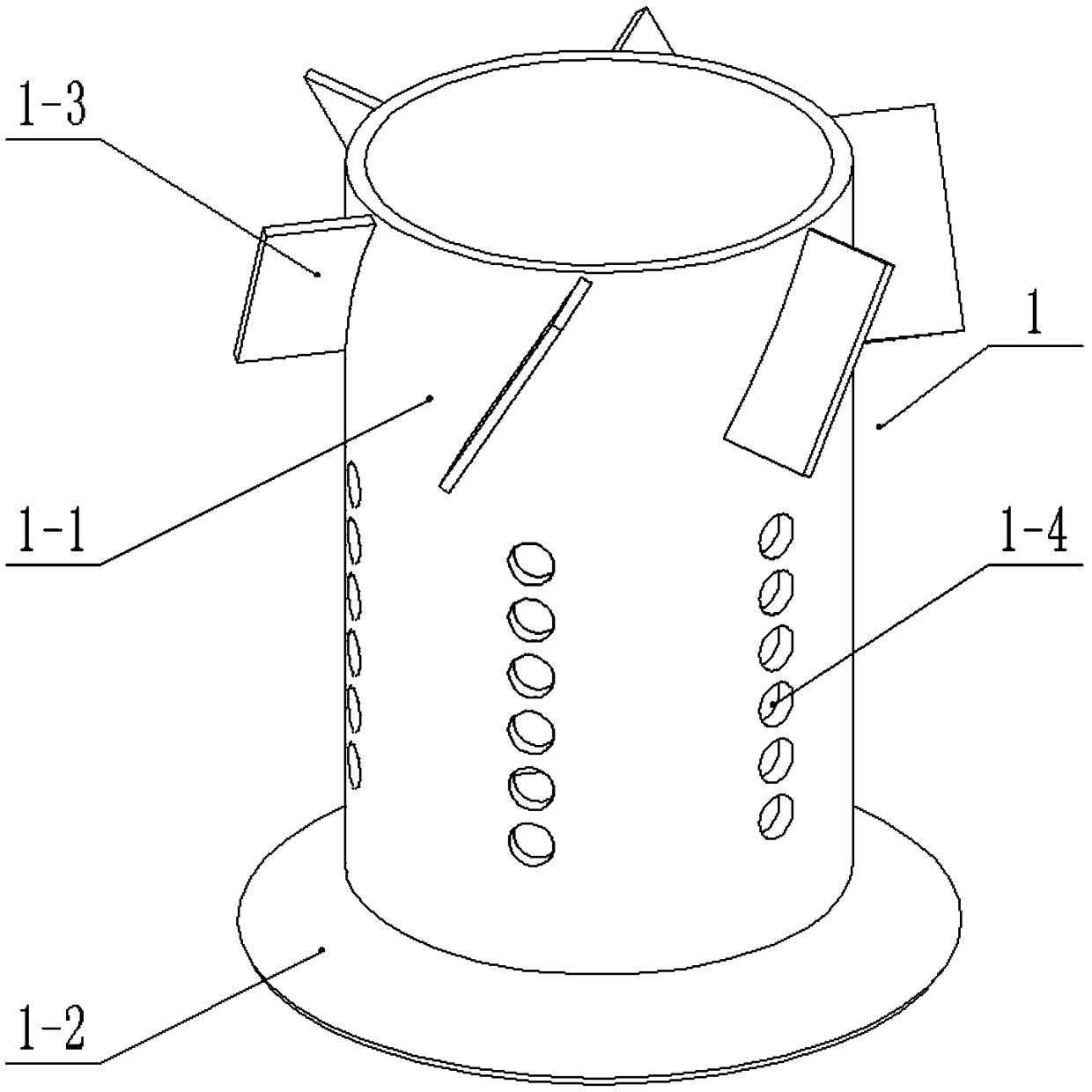
[0031] Combine below Figure 1-10 Describe this embodiment, this embodiment will further explain the first embodiment, the stirring sleeve 1 includes a sleeve 1-1, a cone bucket 1-2, a plurality of return blades 1-3 and a plurality of return holes 1-4, the The cone bucket 1-2 is fixedly connected to the lower end of the sleeve 1-1, and the outer side of the upper end of the sleeve 1-1 is uniformly fixedly connected with a plurality of return blades 1-3, and the middle end of the sleeve 1-1 is provided with A plurality of reflux holes 1-4 evenly distributed in the radial direction, the oil flow drives the internal rotation component 4 to rotate, and the rotation of the internal rotation component 4 drives the rotation of the stirring sleeve 1, and the stirring sleeve 1 rotates through multiple return blades 1-3 to make the stirring The oil at the upper end of the sleeve 1 flows downward through the outside of the sleeve 1-1, and finally flows into the sleeve 1-1 through a plura...
specific Embodiment approach 3
[0032] Combine below Figure 1-10Describe this embodiment, this embodiment will further explain Embodiment 2, the oil seal sleeve 2 includes an oil seal ring 2-1, an oil seal inner connection sleeve 2-2, a support ring 2-3 and a retaining ring 2-4 , the oil sealing inner connecting sleeve 2-2 is fixedly connected inside the oil sealing ring 2-1, the oil sealing ring 2-1 is slidingly connected inside the sleeve 1-1, and the oil sealing inner connecting sleeve 2 -2 is fixedly connected to the viscosity reducer delivery pipe 3, the support ring 2-3 is fit in the oil sealing ring 2-1, and the support ring 2-3 is located at the upper end of the oil sealing inner connecting sleeve 2-2, The retaining ring 2-4 is fixedly connected to the inner upper end of the oil sealing ring 2-1; the oil sealing ring 2-1 blocks part of the return hole 1-4 located at the lower end, and when the stirring sleeve 1 slides upward, it is connected to the sleeve The number of return holes 1-4 inside the s...
PUM
 Abstract
Description
Claims
Application Information
 - Generate Ideas
- Intellectual Property
- Life Sciences
- Materials
- Tech Scout
- Unparalleled Data Quality
- Higher Quality Content
- 60% Fewer Hallucinations
Browse by: Latest US Patents, China's latest patents, Technical Efficacy Thesaurus, Application Domain, Technology Topic, Popular Technical Reports.
© 2025 PatSnap. All rights reserved.Legal|Privacy policy|Modern Slavery Act Transparency Statement|Sitemap|About US| Contact US: help@patsnap.com