
Ribbon for edge press printer and manufacturing method thereof

A technology for printers and a production method, which is applied in printing, ink ribbons, inking devices, etc., can solve the problems of poor high temperature resistance and anti-sticking effect of high temperature resistant coatings, easy discoloration of the film surface, etc., and achieve excellent powder shedding performance of the coating , Avoid coating powder drop, high resolution effect

Active Publication Date: 2020-10-09
南京爱宝文仪有限公司
View PDF7 Cites 0 Cited by
  • Summary
  • Abstract
  • Description
  • Claims
  • Application Information

AI Technical Summary

Problems solved by technology

Although there have been some achievements in the preparation of thermal transfer ribbons for edge pressure and high-speed printing at home and abroad, but for the combination of thermal transfer ribbons for edge pressure and high-speed printing and the usability of the visual function after printing, to The development and production of high-speed printing of labels and flexible packaging materials that meet some special requirements for printing and imprinting are still blank, because they are subject to research on the formulation of thermal transfer printing inks, research on coating technology, and advanced mass production equipment technology and quality. Constraints of common key technical problems in process control and other industries
The film surface of the existing carbon belt is relatively sticky, and the film surface is easy to change color under high temperature, and the high temperature resistant coating on the back has poor high temperature resistance and anti-sticking effect

Method used


Image

  • Ribbon for edge press printer and manufacturing method thereof

Examples


Embodiment

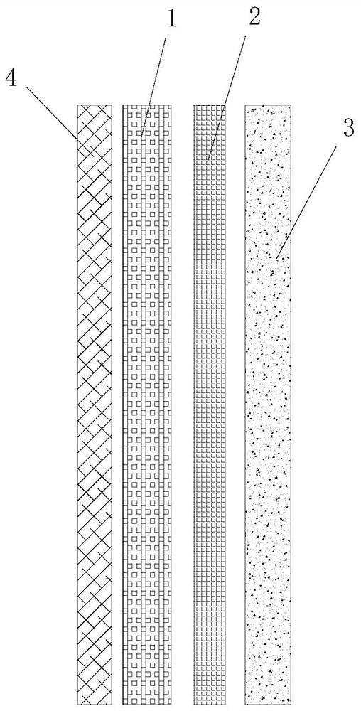
[0027] Such as figure 1 As shown, a carbon ribbon for an edge press printer includes a base film 1, a release layer 2, a thermal transfer ink layer 3 and a heat-resistant layer 4 arranged in sequence; wherein,

[0028] The base film 1 is a biaxially stretched polyester film with a thickness of 3.5-4.5um without corona treatment;

[0029] The release layer 2 is composed of 40-60% by weight of Brazilian wax, 40-60% by weight of synthetic wax and 10-20% by weight of ethylene-vinyl acetate copolymer;

[0030] The thermal transfer ink layer 3 is composed of 10-30% by weight of resin, 0.5-4% by weight of auxiliary agent, 10-20% by weight of pigment and 50-70% by weight of solvent;

[0031] The heat-resistant layer 4 is composed of 20-30% by weight of polyester resin, 1-3% by weight of TDI curing agent and 70-80% of MEK solvent.

[0032] The melting point of the release layer 2 is 70-90°C.

[0033] The synthetic wax is selected from one or more of natural wax, animal wax and arti...


PUM

PropertyMeasurementUnit
Thicknessaaaaaaaaaa
Melting pointaaaaaaaaaa

Abstract

The invention provides an edge rolling type thermal transfer ribbon for a printer and a manufacturing method thereof. The edge rolling type thermal transfer ribbon comprises a base film, a release layer, a thermal transfer printing ink layer and a heat resisting layer, wherein the thermal transfer printing ink comprises 10-30% by weight of resin, 0.5-4% by weight of additive, 10-20% by weight of pigment, and 50-70% by weight of solvent; the temperature of the solvent is increased, and thus the solvent is heated and the resin is dissolved to prepare resin liquid; the resin liquid is fully mixedwith the pigment and the additive and then is milled into the printing ink through a horizontal sand mill; a release coating coats the base film, and 3.2-4.0g of release coating coats the base film per square; the printing ink coats the surface of the release layer, and 1.8-2.5g printing ink coats the surface per square; and the heat resisting coating coats the other layer of the base film, and 0.1-1.0g of heat resisting coating coats the other layer per square. With the adoption of the thermal transfer ribbon, an image printed through the printer has the advantages of being high in resolution, resistant to friction, and resistant to ageing; the printing speed is up to 24inch / S, so that the requirement of ultrahigh-speed printing is met.

Description

technical field [0001] The invention belongs to the technical field of thermal transfer carbon ribbons, and relates to a carbon ribbon for edge press printers and a manufacturing method thereof. Background technique [0002] Ribbon is a printing consumable that is widely used at present. From the earliest mechanical impact type English printers to the later computer dot matrix printers, carbon ribbons are used. The working principle of the carbon ribbon is to use the dot matrix striker in the head of the dot matrix printer or the letter striker in the English typewriter to hit the printing ribbon to produce a printing effect on the printing paper. [0003] With the development of the market economy, the application of thermal transfer printing technology in various industries has become more and more extensive and mature, and the corresponding requirements for printing effects and work efficiency have also increased, and the demand for high-speed printing has become more an...

Claims


Application Information

Patent Timeline
IPC IPC(8): B41J31/05B41J31/00
CPCB41J31/00B41J31/05
Inventor 薛中林薛兵彬
Owner 南京爱宝文仪有限公司
Learn More