Demolding assembly and method for beam

A demoulding and assembly technology, applied in the direction of unloading devices, manufacturing tools, etc., can solve the problems of high damage rate and low demoulding efficiency of beams, and achieve the effect of stable contact and simple and easy-to-operate adjustment mechanism

Pending Publication Date: 2018-09-28
ANHUI JIALIQI AEROSPACE CARBON FIBER CO LTD
View PDF9 Cites 2 Cited by
  • Summary
  • Abstract
  • Description
  • Claims
  • Application Information

AI Technical Summary

Problems solved by technology

[0003] The technical problem to be solved by the present invention is that the demoulding efficiency of beams in the prior art is low and the damage rate is high

Method used


Image

  • Demolding assembly and method for beam
  • Demolding assembly and method for beam
  • Demolding assembly and method for beam

Examples


Embodiment Construction

[0031] In order to have a further understanding and understanding of the structural features of the present invention and the achieved effects, the preferred embodiments and accompanying drawings are used for a detailed description, as follows:

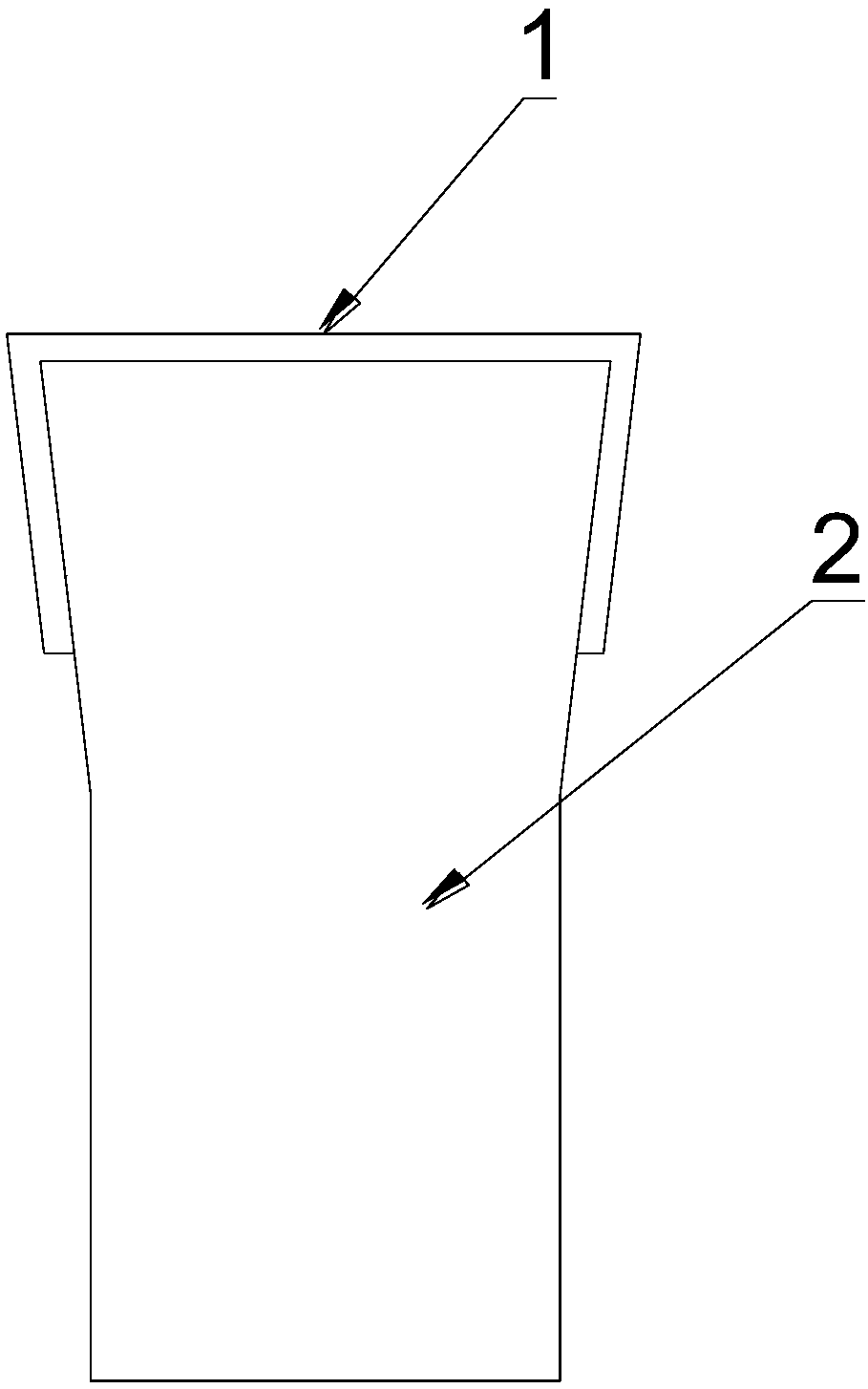
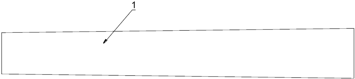
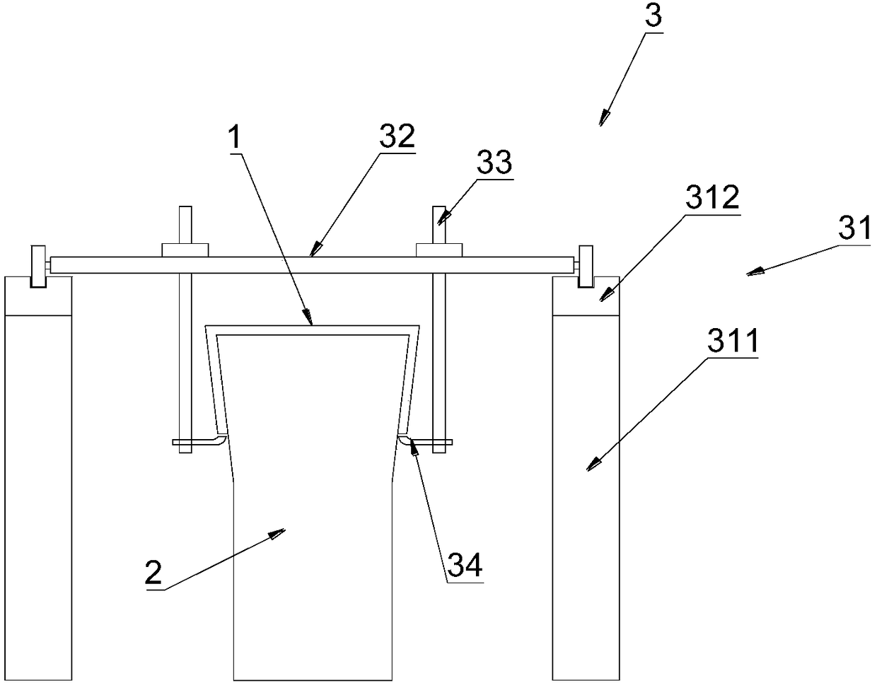
[0032] Such as figure 2 , image 3 As shown, a demoulding assembly for beams includes a lifting mechanism 3 for beams 1 and a separating and pushing mechanism 4 for beams 1 . The beam 1 is buckled on the mold 2 .

[0033] The lifting mechanism 3 includes a bracket 31 and a moving beam 32 fixed on the first bracket 31; the bracket 31 includes rails 312 fixed on both sides of the beam 1 through a vertical rod 311, and the moving beam 32 is perpendicular to the axis of the beam 1 Crossing the beam 1 ; the two ends of the moving beam 32 are fixed with rollers 321 that cooperate with the track, so that the moving beam 32 can move forward and backward along the axis of the beam 1 . A lifting part is fixed on the moving beam 32, and the ...


PUM

PropertyMeasurementUnit
thicknessaaaaaaaaaa

Abstract

The invention provides a demolding assembly and method for a beam. The demolding assembly comprises a beam lifting mechanism and a beam separation and push mechanism. The beam lifting mechanism comprises a support and a movable beam fixed to the first support, the movable beam is perpendicular to the axial line of the beam to stretch across a beam mold, the movable beam can move front and back inthe axial line of the beam, a lifting portion is fixed to the movable beam, the lifting portion drives the beam to ascend, and therefore a gap is formed between the beam and a mold. The separation andpush mechanism comprises a gasket and a push portion. The gasket is inserted into the gap between the beam and the mold from one end, the gasket is pushed by the push mechanism, and the beam is separated from the mold; and the push portion jacks the end of the beam for jacking, and the beam is moved towards the other end. The movable beam can move on the first support, after the beam is lifted, the movable moves forwards along with the beam under the push of the push portion, no additional resistance force is caused to the beam, the demolding process is smoother, and the beam damage rate is greatly reduced.

Description

technical field [0001] The invention relates to the technical field of demoulding of composite material products, in particular to a demoulding assembly and a demoulding method of a beam. Background technique [0002] Such as figure 1 , figure 2 As shown, the beam includes the web and the flanges on both sides of the web, the angle between the flange and the web is less than 90°, one end of the beam is a large end, and the other end is a variable diameter structure; the beam buckle On the mold; the cross-section of the mold is also a structure with a wide top and a narrow bottom. As a result, it is necessary to push the beam from the large end to the small end when demoulding. During the demoulding process, it is easy to cause beam damage. Contents of the invention [0003] The technical problem to be solved by the invention is that the demoulding efficiency of beams in the prior art is low and the damage rate is high. [0004] The present invention solves the above ...

Claims


Application Information

Patent Timeline
Patent Type & Authority Applications(China)
IPC IPC(8): B28B13/06
CPCB28B13/06
Inventor 路强蔡天琪候琪
Owner ANHUI JIALIQI AEROSPACE CARBON FIBER CO LTD
Why Eureka
Try Eureka