Clamp transformation mechanism for large machine tool

A technology of converting mechanism and large machine tool, applied in the direction of clamping, manufacturing tools, metal processing machinery parts, etc., can solve the problems of waste of large machining centers, inability to clamp and fix, and achieve the effect of improving production efficiency and utilization rate

Active Publication Date: 2018-09-28
WANFENG MERIDIAN LIGHTWEIGHT TECH CO LTD
View PDF16 Cites 0 Cited by
  • Summary
  • Abstract
  • Description
  • Claims
  • Application Information

AI Technical Summary

Problems solved by technology

[0002] Existing aluminum alloy parts for automobiles, such as automobile steering column brackets, need to be processed after casting, and because they are small parts, they cannot be clamped and fixed on large machine tools in large machining centers. For processing, it can only be processed in the machining center of the small machine tool, and the time used by the large machining center is not as much as that of the small machining center, and it will generate idle time. At this time, the large machining center will generate waste

Method used


Image

  • Clamp transformation mechanism for large machine tool
  • Clamp transformation mechanism for large machine tool
  • Clamp transformation mechanism for large machine tool

Examples


Embodiment Construction

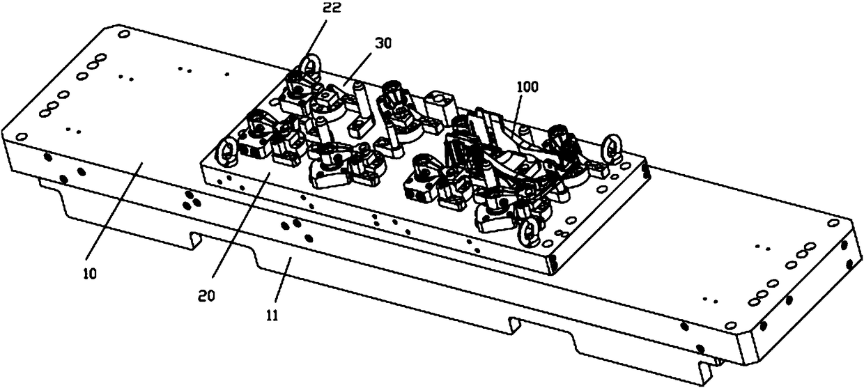
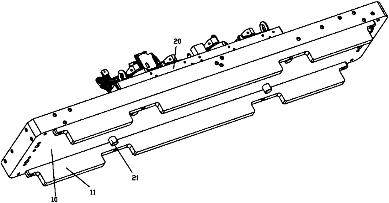
[0024] Examples, see e.g. Figure 1 to Figure 5 As shown, a clamp conversion mechanism for a large machine tool, which includes a fixed main aluminum plate 10, the middle top surface of the fixed main aluminum plate 10 is pressed against a bridge plate 20, and the front and rear parts of the left and right sides of the bottom surface of the bridge plate 20 are both A positioning column 21 is fixed, and the positioning column 21 is inserted into the positioning socket formed in the middle of the fixed main aluminum plate 10;

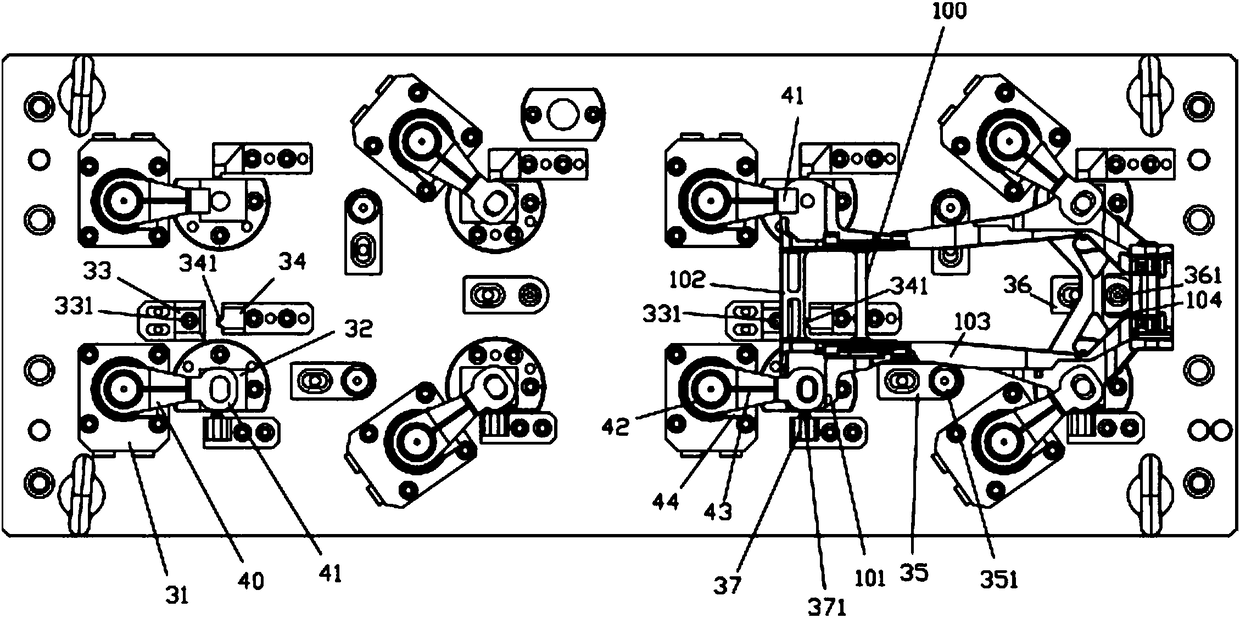
[0025] At least two sets of clamping mechanisms 30 are installed on the top surface of the bridge plate 20;

[0026] The clamping mechanism 30 includes a plurality of pressing and fixing cylinders 31, the upper part of the pressing and fixing cylinders 31 is fixed on the top surface of the bridge plate 20, and the cylinder body of the pressing and fixing cylinders 31 is inserted into the vertical passage of the bridge plate 20. In the hole, the end of th...


PUM


Abstract

The invention discloses a clamp transformation mechanism for a large machine tool. The mechanism comprises a fixed main aluminum plate, a bridge plate abuts against the top face of the middle of the fixed main aluminum plate in a pressing mode, positioning columns are fixed to the front portions and the rear portions of the left side and the right side of the bottom face of the bridge plate correspondingly, the positioning columns are inserted into positioning inserting holes formed in the middle of the fixed main aluminum plate in a sleeved mode, the top face of the bridge plate is provided with at least two sets of clamping mechanisms, each set of clamping mechanism comprises multiple pressing fixed air cylinders, the upper portions of the pressing fixed air cylinders are fixed to the top face of the bridge plate, cylinder bodies of the pressing fixed air cylinders are inserted into vertical through holes in the bridge plate in a sleeved mode, and pressing arms are fixed to the endsof push rods of the pressing fixed air cylinders. The fixed main aluminum plate can be fixed to the large machine tool of a large machining center, the bridge plate is installed on the fixed main aluminum plate, the clamping mechanisms installed on the bridge plate can accurately position, clamp and fix small aluminum parts to be clamped, therefore, the large machining center can machine the aluminum parts to be clamped, the using ratio is improved, and idling is avoided.

Description

Technical field: [0001] The invention relates to the technical field of auto parts processing, in particular to a fixture conversion mechanism for a large machine tool. Background technique: [0002] Existing aluminum alloy parts for automobiles, such as automobile steering column brackets, need to be processed after casting, and because they are small parts, they cannot be clamped and fixed on large machine tools in large machining centers. For processing, it can only be processed in the machining center of the small machine tool, and the time used by the large machining center is not as much as that of the small machining center, which will generate idle time. At this time, the large machining center will generate waste. Invention content: [0003] The purpose of the present invention is to overcome the deficiencies of the prior art, and provide a clamp conversion mechanism for large machine tools, which can fix the fixed main aluminum plate on the large machine tool of ...

Claims


Application Information

Patent Timeline
Patent Type & Authority Applications(China)
IPC IPC(8): B23Q3/06
CPCB23Q3/06Y02P70/10
Inventor 陈雷王利鹏郝晓伟吴志勇徐国锋
Owner WANFENG MERIDIAN LIGHTWEIGHT TECH CO LTD
Why Eureka
Try Eureka