Airplane environment control and fuel tank inerting coupled system and method based on membrane separation method

一种膜分离法、耦合系统的技术,应用在分离方法、化学仪器和方法、飞机零件等方向,能够解决部件多、重量大、结构复杂等问题,达到系统结构简单、制冷量大、提升性能的效果

Active Publication Date: 2018-09-25
BEIHANG UNIV
View PDF7 Cites 21 Cited by
  • Summary
  • Abstract
  • Description
  • Claims
  • Application Information

AI Technical Summary

Problems solved by technology

The system has high water removal efficiency and large cooling capacity, but has many components, complex structure and heavy weight

Method used


Image

  • Airplane environment control and fuel tank inerting coupled system and method based on membrane separation method
  • Airplane environment control and fuel tank inerting coupled system and method based on membrane separation method
  • Airplane environment control and fuel tank inerting coupled system and method based on membrane separation method

Examples


Embodiment Construction

[0062] The aircraft environment control and fuel tank inerting coupling system based on the membrane separation method according to an embodiment of the present invention will be described in detail below with reference to the accompanying drawings. But the scope of protection of the present invention is not limited to the following examples.

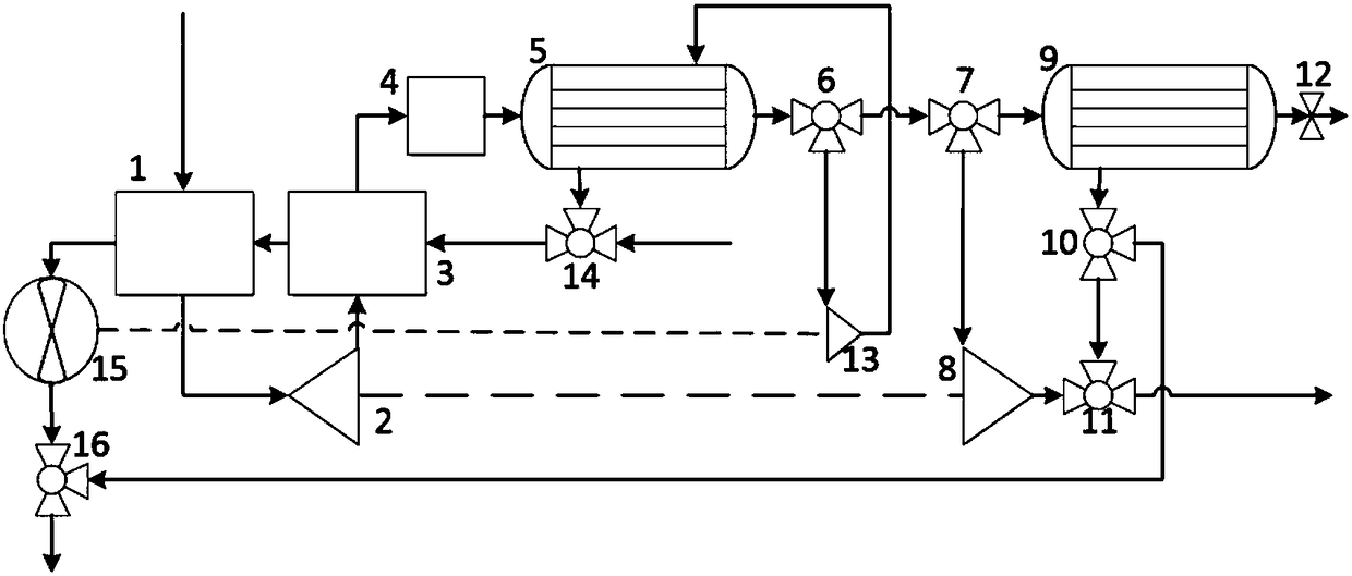
[0063] Such as figure 1 The shown aircraft environment control and fuel tank inert coupling system based on the membrane separation method according to an embodiment of the present invention includes: primary heat exchanger (1), supercharger (2), secondary heat exchanger (3) , filter (4), membrane dehumidification heat exchanger (5), first three-way valve (6), second three-way valve (7), large expansion turbine (8), membrane air separator (9), the first Three three-way valve (10), fourth three-way valve (11), flow limiting valve (12), small expansion turbine (13), fifth three-way valve (14), fan (15), sixth three-way valve (16). Wher...


PUM


Abstract

The invention provides an airplane environment control and fuel tank inerting coupled system based on a membrane separation method. The system is characterized in that gas dehumidification in an airplane environment control system and oxygen and nitrogen separation in a fuel tank inerting system are achieved respectively by the oxygen / nitrogen permselectivity of membranes; one part of dry gas passing a membrane dehumidification heat exchanger enters a membrane air separator, and the other part of the dry gas is subjected to turbine expansion cooling and then fed into a cockpit to perform refrigerating; nitrogen-enriched gas generated by the membrane air separator is fed into a fuel tank to perform inerting, and oxygen-enriched gas is mixed with gas supplied by the environment control system to increase the oxygen content of gas supplied for the cockpit. Compared with the independent environment control system and fuel tank inerting system of an existing airplane, the coupled system hasthe advantages that the coupled system is simple in structure, lightweight, capable of sufficiently utilizing an engine to guide gas and increasing the oxygen content of gas supplied for the cockpitand capable of reducing system compensatory loss, and the thermodynamic property of the coupled system is also better than that of the two independent systems.

Description

technical field [0001] The invention proposes an aircraft environment control and fuel tank inerting coupling system and method based on a membrane separation method. Background technique [0002] When the aircraft works in a high-humidity environment, water vapor will have a negative impact on the aircraft's environmental control system, so the air needs to be dehumidified in the aircraft's environmental control system. At present, all advanced aircrafts in the world adopt high-pressure water-removing environmental control systems. The system has high water removal efficiency and large cooling capacity, but has many components, complex structure and heavy weight. [0003] The high-pressure air membrane dehumidification technology relies on the water vapor partial pressure difference on both sides of the membrane to drive the water vapor to diffuse across the membrane. Therefore, the dehumidification process does not require water vapor to condense and release heat, which a...

Claims


Application Information

Patent Timeline
Patent Type & Authority Applications(China)
IPC IPC(8): B01D53/26B01D46/00B64D13/06B64D37/32
CPCB01D46/00B01D53/268B01D2257/80B01D2259/4566B64D13/06B64D37/32B64D2013/0662B01D2053/224B01D2256/10B01D2257/104B01D2259/4575B64D2013/0651B64D2013/0677Y02T50/40Y02T50/50B01D53/226B64D2013/0618B64D2013/0681
Inventor 袁卫星郑妍尉斌
Owner BEIHANG UNIV
Why Eureka
Try Eureka