
Cooling device for bearing and sliding ring of doubly fed wind driven generator

A technology for wind turbines and cooling devices, applied in cooling/ventilation devices, electromechanical devices, casings/covers/supports, etc., can solve the problems of reduced bearing life, locked bearings, easy accumulation of carbon powder, etc.

Pending Publication Date: 2018-09-21
SINOPAL (QINGDAO) ELECTRIC CO LTD
View PDF4 Cites 4 Cited by
  • Summary
  • Abstract
  • Description
  • Claims
  • Application Information

AI Technical Summary

Problems solved by technology

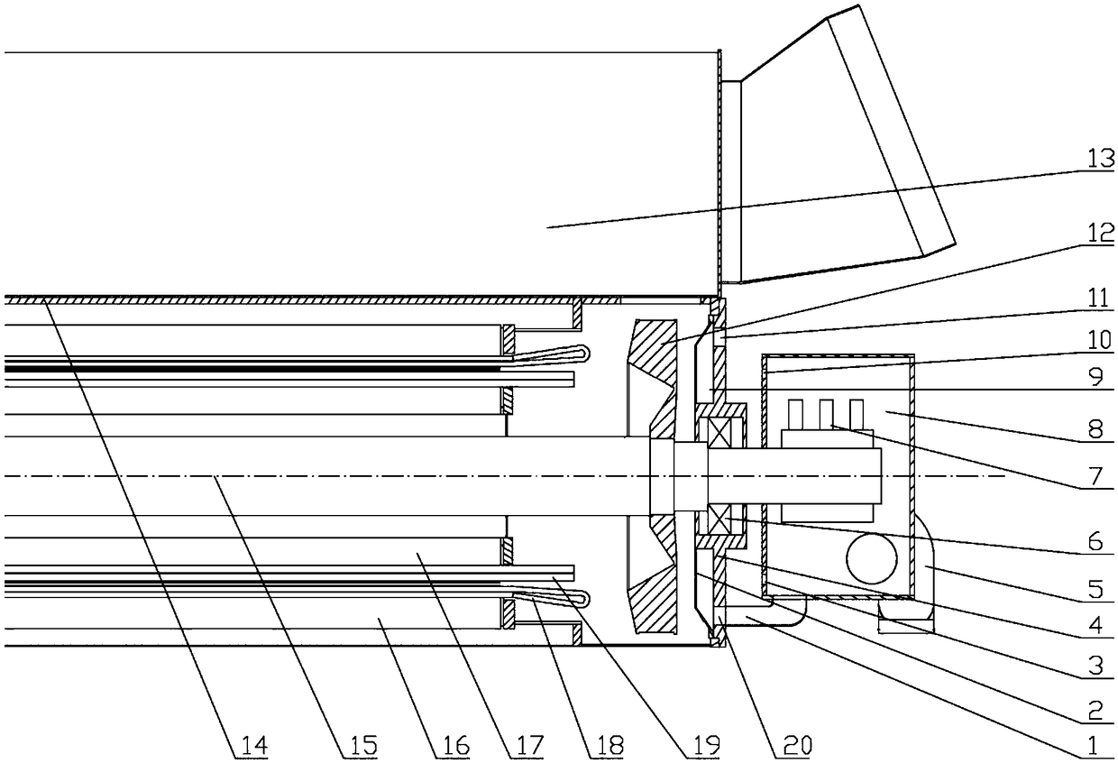
[0005] Aiming at the shortcomings in the above-mentioned existing production technology, the applicant provides a cooling device for the bearing and slip ring of the doubly-fed wind power generator, which solves the problem of the bearing on the side of the centrifugal fan of the doubly-fed wind power generator shaft during operation. The temperature is very high, causing the bearing to lock and the bearing life to be reduced. On the other hand, it solves the problem of short circuit between the slip ring and the carbon brush caused by the easy accumulation of toner in the slip ring chamber and the poor removal of toner, which greatly improves the reliability of use. good cooling effect

Method used


Image

  • Cooling device for bearing and sliding ring of doubly fed wind driven generator
  • Cooling device for bearing and sliding ring of doubly fed wind driven generator
  • Cooling device for bearing and sliding ring of doubly fed wind driven generator

Examples


Embodiment Construction

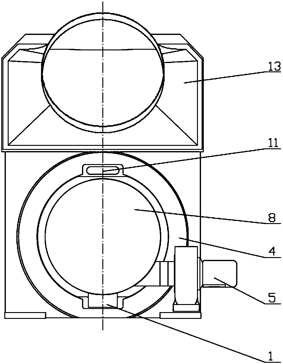
[0020] Such as figure 1 , figure 2 , image 3 As shown, the cooling device of the bearing and the slip ring of the double-fed wind power generator of the present embodiment includes a main shaft 15, and one end of the main shaft 15 is installed with the motor end cover 4 through the bearing 6, and the inside of the motor end cover 4 is installed with the windshield 2, A windshield chamber 9 is formed between the windshield 2 and the motor end cover 4, and the end surface of the motor end cover 4 is provided with a windshield chamber air inlet hole 11 and a windshield chamber air outlet hole 20, and the windshield chamber air outlet The hole 20 is connected to the slip ring chamber 8 through the air duct 1, and the outer wall of the slip ring chamber 8 is installed with a fan 5; one end of the main shaft 15 is installed with a slip ring and a carbon brush 7, and placed in the slip ring chamber 8; The side wall of the slip ring chamber 8 is provided with a first air inlet hol...


PUM


Abstract

The invention relates to a cooling device for a bearing and a sliding ring of a doubly fed wind driven generator. The device comprises a main shaft, one end of the main shaft penetrates through a bearing installing motor end cover, a wind blocking hood is arranged on the inner side of the motor end cover, a wind blocking hood cavity is formed in the part between the wind blocking shield and the motor end cover, a wind blocking hood cavity inlet and a wind blocking hood cavity outlet are formed in the end face of the motor end cover, the wind blocking hood cavity outlet is communicated with a sliding ring chamber through a wind induction pipe, and a ventilation fan is installed on the outer side wall of the sliding ring chamber; the sliding ring and a carbon brush are installed at one end of the main shaft and embedded in the sliding ring chamber; a sliding ring chamber first air inlet and a sliding ring chamber second air inlet are formed in the side wall of the sliding ring chamber. The structure of the cooling device is simple, the problem of excessively high temperature during the operation process of a bearing on the side of a shaft band centrifugal fan of the doubly fed wind driven generator resulting in the locking of the bearing and the reduction of the service life of the bearing is solved, the cooling effect on the sliding ring and the carbon brush can be ensured, carbon powder in the sliding ring chamber does not easily accumulate, and the problem of the short circuit of the sliding ring and the carbon brush due to the fact that the carbon powder is not dischargedsmoothly is solved.

Description

technical field [0001] The invention relates to the technical field of motor cooling devices, in particular to a cooling device for bearings and slip rings of a double-fed wind power generator. Background technique [0002] At present, in order to enhance the heat dissipation capacity of the doubly-fed wind turbine, a shaft centrifugal fan is usually installed at one end of the motor. Although the shaft centrifugal fan increases the air volume of the motor's internal air circulation and enhances the heat dissipation capacity of the motor, the air flow in the internal air passage of the shaft centrifugal fan absorbs the heat generated by the motor winding and iron core, resulting in a high temperature. The high-temperature airflow bakes the bearing on the side of the shaft with centrifugal fan. The heat dissipation environment of the bearing on this side is poor. Since the bearing also generates heat during operation, the temperature of the bearing on this side is very high d...

Claims


Application Information

Patent Timeline
IPC IPC(8): H02K9/28H02K9/04H02K9/06H02K5/04H02K5/20
CPCH02K5/04H02K5/20H02K9/04H02K9/06H02K9/28
Inventor 杨海江仇巍张娜娜王瑞芹黄森林
Owner SINOPAL (QINGDAO) ELECTRIC CO LTD
Learn More