
Connector for installing optical fiber

A technology for installation and connectors, which is applied in the direction of light guides, optics, instruments, etc., can solve the problems of easy deviation of optical fiber orientation, difficult connector fixation, and connector shaking, so as to increase the use range, reduce shaking, and avoid wear and tear Effect

Pending Publication Date: 2018-09-21
范媛媛
View PDF7 Cites 2 Cited by
  • Summary
  • Abstract
  • Description
  • Claims
  • Application Information

AI Technical Summary

Problems solved by technology

[0005] The purpose of the present invention is to provide a connector for optical fiber installation to solve the problem that the orientation of the optical fiber is easy to shift when the existing optical fiber connector proposed in the background technology is used, and it is difficult to fix the position of the connector. The connector is prone to greater shaking, and at the same time, the outer side is prone to cause more wear and tear

Method used


Image

  • Connector for installing optical fiber
  • Connector for installing optical fiber
  • Connector for installing optical fiber

Examples


Embodiment Construction

[0023] The following will clearly and completely describe the technical solutions in the embodiments of the present invention with reference to the accompanying drawings in the embodiments of the present invention. Obviously, the described embodiments are only some, not all, embodiments of the present invention. Based on the embodiments of the present invention, all other embodiments obtained by persons of ordinary skill in the art without making creative efforts belong to the protection scope of the present invention.

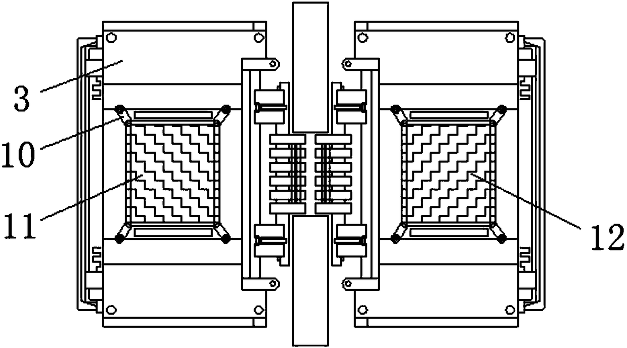
[0024] see Figure 1-5 , the present invention provides a technical solution: a connector for optical fiber installation, including a first protective rod 1, a buffer column 2, a first connecting plate 3, a limit card slot 4, a connecting block 5, a separation bar 6, a mounting plate 7. The second connecting plate 8, the second protective rod 9, the locking plate 10, the first soft layer 11, the second soft layer 12, the first threaded groove 13, the spacer 14...


PUM


Abstract

The invention relates to a connector for installing an optical fiber. The connector comprises a first protection rod and a limiting clamping slot. A buffer column is fixed on an inner side of the first protection rod, and a bottom end of the buffer column is connected to a first connection plate. The limiting clamping slot is arranged on an outer wall of the first connection plate, and a right endof the first connection plate is provided with connection blocks. Separating bars are installed between the connection blocks, and mounting plates are fixed on upper and lower sides of the separatingbars. A second connection plate is arranged on the right sides of the mounting plates, a second protection rod is embedded in the right end of the second connection plate, and locking plates are embedded around the back surface of the first connection plate. The connector for installing the optical fiber has the advantages that a preliminary protection function is achieved through the second protection rod and the first protection rod, and the external wear due to collision during use is avoided.

Description

technical field [0001] The invention relates to the technical field of optical fiber connectors, in particular to a connector for optical fiber installation. Background technique [0002] Optical fiber connector is a device for detachable (movable) connection between optical fiber and optical fiber. It precisely butts the two end faces of optical fiber so that the optical energy output by the transmitting optical fiber can be coupled to the receiving optical fiber to the maximum extent. And to minimize the impact on the system due to its intervention in the optical link, this is the basic requirement of the fiber optic connector. To a certain extent, fiber optic connectors affect the reliability and performance of optical transmission systems. [0003] The main purpose of fiber optic connectors is to realize the splicing of optical fibers. Optical fiber connectors that have been widely used in optical fiber communication systems now have many types and different structures...

Claims


Application Information

Patent Timeline
Patent Type & Authority Applications(China)
IPC IPC(8): G02B6/38
CPCG02B6/3849G02B6/3855
Inventor 罗诗敏柴霞霞周鹏陈昊李闻淼
Owner 范媛媛
Learn More