Clamping device for chemical membrane optical element

A clamping device and optical element technology, applied in the direction of load hanging element, transportation and packaging, etc., can solve the problems of easy damage, no physical film wipeability, lack of self-healing ability, etc., to achieve reliable connection, The effect that the technical indicators are not reduced and the cleanliness is not polluted

Pending Publication Date: 2018-09-21
LASER FUSION RES CENT CHINA ACAD OF ENG PHYSICS
View PDF4 Cites 0 Cited by
  • Summary
  • Abstract
  • Description
  • Claims
  • Application Information

AI Technical Summary

Problems solved by technology

In view of the fact that the chemical film is a kind of soft film, it does not have the wipeability of the physical film, it is easily damaged in the corrosive liquid, and it lacks self-healing ability

Method used


Image

  • Clamping device for chemical membrane optical element
  • Clamping device for chemical membrane optical element
  • Clamping device for chemical membrane optical element

Examples


Embodiment 1

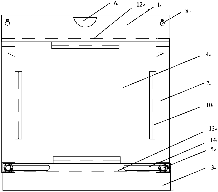
[0039] The assembly process of the optical element clamping device of the present invention is as follows:

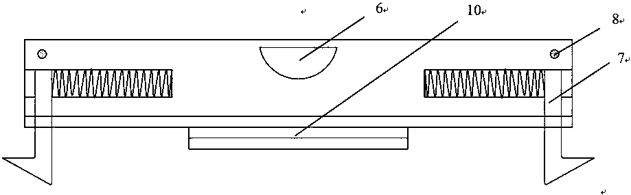
[0040] Place the chemical film optical element to be clamped in the U-shaped clamping groove of the load-bearing beam 3, and then move the clamping beam 2 along the sliding groove 13 of the load-bearing beam 3 according to the specific size of the chemical film optical element until The U-shaped clamping groove of the clamping beam 2 fits the chamfering edge of the chemical film optical element, and the load-bearing beam 3 is fixedly connected with the two clamping beams 2 through the positioning bolt 5; then the lifting beam 1 is placed on the exposed chemical film optical element On the side wall, turn off the adjustment switch 7 to fix the chemical film optical element in the clamping device, so as to ensure that the chemical film optical element does not move in the three-dimensional space. Then the sealing plate 4 is installed, and the loading and unloading of the ...


PUM


Abstract

The invention discloses a clamping device for a chemical membrane optical element. The clamping device comprises a hanging beam, clamping beams, a bearing beam and sealing plates; the hanging beam, the clamping beams and the bearing beam form a square frame, the bottom frame is the bearing beam, the left frame and the right frame are the two oppositely arranged clamping plates, and the top frame is the hanging beam; the inner sides of the hanging beam, the clamping beams and the bearing beam are provided with clamping grooves; the sealing plates are fixed to the front and the back of the square frame through sealing plate bolts on the hanging beam; the clamping device for the chemical membrane optical element is adjustable, clean delivery of the chemical membrane optical element in the operation processes such as transportation, storing, transfer, inspection and surface observation can be kept, non-contact operation of the optical element light transmission surface is achieved, stressuniformity of the optical element in the clamping process is protected, and additional pollution and stress are not likely to be generated. The clamping device for the chemical membrane optical element is suitable for optical elements of various specifications and shapes to use.

Description

technical field [0001] The invention belongs to the field of high-energy and high-power large-scale laser devices, and in particular relates to a clamping device for chemical film optical elements. Background technique [0002] In large-scale laser devices, laser optical thin films can be divided into two types according to the preparation method, namely physical method (vacuum evaporation method) and chemical method (including chemical vapor deposition and chemical solution deposition). With the gradual upgrading of inertial confinement fusion (ICF) high-power solid-state laser devices, higher requirements are put forward for the laser load capacity of optical thin films. At the same time, the coating of large-aperture optical components and reasonable economic problems have become insurmountable by traditional physical coatings. difficulties. Sol-gel chemical coating has attracted great interest from ICF research institutions in various countries due to its low cost, simp...

Claims


Application Information

Patent Timeline
Patent Type & Authority Applications(China)
IPC IPC(8): B66C1/42
CPCB66C1/42
Inventor 叶琳程晓锋杨存榜
Owner LASER FUSION RES CENT CHINA ACAD OF ENG PHYSICS
Why Eureka
Try Eureka