Efficient pile foundation engineering piling device with fixed size convenient to adjust

A piling device and a fixed-size technology, which is applied in the direction of foundation structure engineering, sheet pile walls, buildings, etc., can solve the problems of inability to adjust the fixed size, low piling efficiency, etc.

Inactive Publication Date: 2021-07-06
江苏苏中建设集团岩土工程有限公司
View PDF7 Cites 0 Cited by
  • Summary
  • Abstract
  • Description
  • Claims
  • Application Information

AI Technical Summary

Problems solved by technology

[0004] The purpose of the present invention is to solve the shortcomings of existing piling machines that cannot adjust the fixed size during the piling process, resulting in pile foundations of different sizes needing different piling machines for piling, and at the same time, the piling efficiency is low. A high-efficiency piling device for pile foundation engineering that is convenient for adjusting the fixed size

Method used


Image

  • Efficient pile foundation engineering piling device with fixed size convenient to adjust
  • Efficient pile foundation engineering piling device with fixed size convenient to adjust
  • Efficient pile foundation engineering piling device with fixed size convenient to adjust

Examples


Embodiment 1

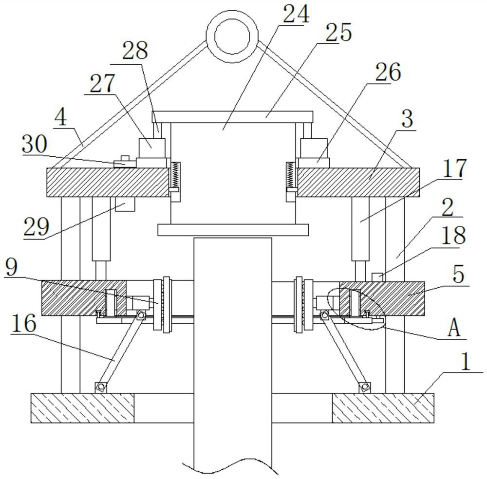
[0028] refer to Figure 1-6 , a high-efficiency piling device for pile foundation engineering that is convenient for adjusting fixed dimensions, comprising a bottom ring 1, two pairs of supporting columns 2 are fixedly installed on the top of the bottom ring 1, and the same top of the two supporting columns 2 is fixedly installed Top plate 3, the top of the top plate 3 is provided with a connecting mechanism 4, the same moving ring 5 is slidingly connected to the two support columns 2, the moving ring 5 is provided with a clamping mechanism, the moving ring 5 is provided with an adjustment mechanism, and the top plate 3 The hammer 24 is slidingly connected, and the top plate 3 is provided with a drive mechanism, which is connected with the hammer 24 in transmission.

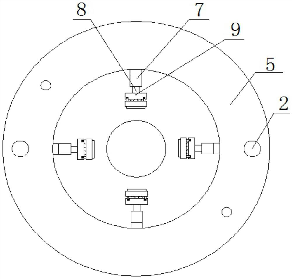
[0029] In this embodiment, the clamping mechanism includes a hydraulic cylinder 17, a sleeve 6, a fixed ring 7, a screw rod 8, a push plate 9, a clamping plate 10, a rubber pad 11 and a hinged rod 16, two hydraul...

Embodiment 2

[0037] refer to Figure 1-6 , a high-efficiency piling device for pile foundation engineering that is convenient for adjusting fixed dimensions, comprising a bottom ring 1, two pairs of supporting columns 2 are welded on the top of the bottom ring 1, and the same top plate 3 is welded on the top of the two supporting columns 2 , the top of the top plate 3 is provided with a connecting mechanism 4, and the same moving ring 5 is slidably connected to the two support columns 2. The moving ring 5 is provided with a clamping mechanism, and the moving ring 5 is provided with an adjustment mechanism. The top plate 3 is slidably connected A percussion hammer 24 is arranged, and the top plate 3 is provided with a drive mechanism, which is connected with the percussion hammer 24 in transmission.

[0038] In this embodiment, the clamping mechanism includes a hydraulic cylinder 17, a sleeve 6, a fixed ring 7, a screw rod 8, a push plate 9, a clamping plate 10, a rubber pad 11 and a hinged...


PUM


Abstract

The invention belongs to the technical field of pile drivers, and particularly relates to an efficient pile foundation engineering piling device with a fixed size convenient to adjust, which aims to solve the problems that pile foundations with different sizes need to be driven by different pile drivers because the fixed size of an existing pile driver cannot be adjusted in the piling process, and additionally, the piling efficiency is low. The following scheme is provided, and the device comprises a bottom ring, wherein two opposite support columns are fixedly installed on the top of the bottom ring, a same top plate is fixedly installed on the top ends of the two support columns, a connecting mechanism is arranged on the top of the top plate, a same movable ring is connected to the two support columns in a sliding mode, a clamping mechanism is arranged on the movable ring, an adjusting mechanism is arranged on the moving ring, a knocking hammer is connected to the top plate in the sliding mode, and a driving mechanism is arranged on the top plate. The device has the advantages of easiness in operation and convenience in use, steel piles can be clamped, and additionally, the clamping size can be adjusted, so that the device can be used for different steel piles.

Description

technical field [0001] The invention relates to the technical field of pile drivers, in particular to a piling device for high-efficiency pile foundation engineering that is convenient for adjusting fixed dimensions. Background technique [0002] Pile foundation engineering refers to burying foundation piles in the ground by beating and watering methods, and reinforcing the overall building above through foundation piles to prevent the collapse of higher-rise buildings, which plays an important role in the quality of houses, among which the pile driver is the foundation Construction machinery is indispensable in pile engineering. With the continuous application of pile drivers, the shortcomings of pile drivers in the process of use are gradually emerging. [0003] Due to the fact that the existing pile driver cannot adjust the fixed size during the piling process, different pile foundations need to be driven by different pile drivers, and the piling efficiency is low. Theref...

Claims


Application Information

Patent Timeline
IPC IPC(8): E02D7/06E02D7/14
CPCE02D7/06E02D7/14
Inventor 郭重霄
Owner 江苏苏中建设集团岩土工程有限公司
Why Eureka
Try Eureka