Low-rise building ecological green space structure and method
A kind of building and low-rise technology, applied in the field of low-rise building ecological green space structure, can solve the problems of entering, aggravating the pressure of drainage facilities, and losing the function of temporary water storage of soil, so as to achieve obvious benefits, improve lodging resistance performance, and high guiding application value Effect
- Summary
- Abstract
- Description
- Claims
- Application Information
AI Technical Summary
Problems solved by technology
Method used
Image
Examples
Embodiment 1
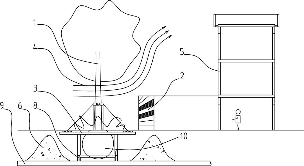
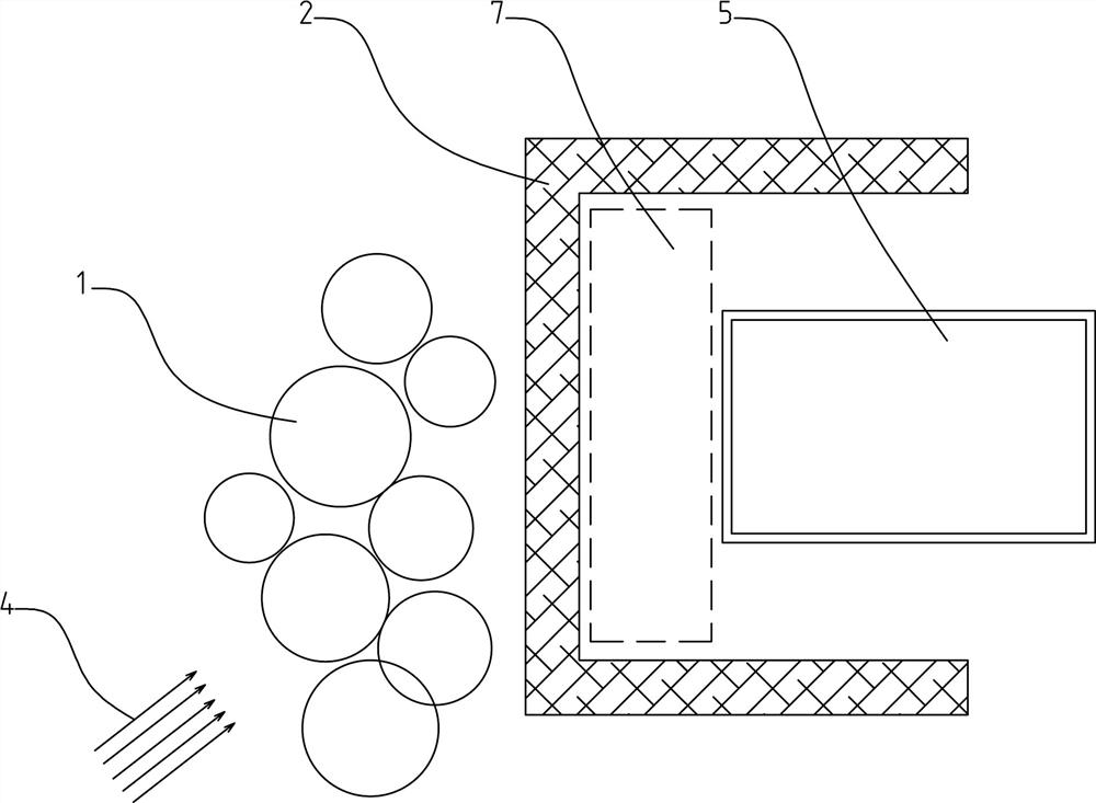
[0045] Such as figure 1 , 2 Among them, an ecological green space structure for low-rise buildings, in which an evergreen hedge 2 is arranged in the direction of the low-rise building 5 facing the dominant wind direction 4 , and an arbor area 1 is arranged outside the evergreen hedge 2 . Based on this structure, the combined structure of the arbor area 1 and the evergreen hedge 2 is used to improve the windproof effect. The dominant wind passes under the canopy of the arbor area 1, encounters the evergreen hedge 2 in the process of advancing, and is guided and dominated by the evergreen hedge 2 The wind rises, thereby avoiding the dominant wind from directly blowing the low-rise building 5, and reducing the heating energy consumption of the low-rise building 5 in winter.
[0046] In this example, the low-rise building 5 refers to a building whose building height is less than or equal to 15 meters and the number of building floors is less than or equal to 4 floors, or refers t...
Embodiment 2
[0057] The existing low-rise buildings 5 are usually located above the base plate 9 and below the base plate 9, and are usually set as garages. That is, the height from the bottom plate 9 to the ground is generally not more than 1.5 meters. Therefore, it is more important to prevent the lodging of trees.
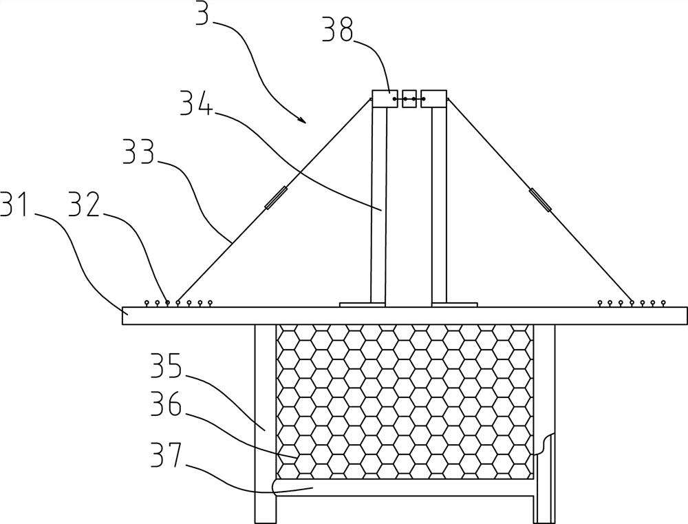
[0058] On the basis of Example 1, the preferred scheme is as figure 1 , 3 , 4, the arbor is also provided with a root-fixing device 3;
[0059] In the described rooting device 3, the rooting frame 31 is buried in the soil, the root ball 10 of the tree is located in the rooting frame 31, and an extension 312 is provided on the outer edge of the rooting frame 31. pull ring 32;
[0060] The upper end of support member 34 is connected with trunk fixing device 38, and trunk fixing device 38 is a ring structure that can be opened and closed, and trunk fixing device 38 is connected with the trunk of arbor, and the lower end of support member 34 is fixedly connected with solid...
Embodiment 3
[0067] On the basis of Examples 1 and 2, further preferred schemes are as figure 1 Among them, a rapid water storage area 6 is arranged underground around the arbor area 1;
[0068] Discarded concrete blocks are buried in the rapid water storage area 6 . Such as figure 1 Among them, the rapid water storage area 6 in this example adopts a natural accumulation structure arranged on the periphery of the arbor root system. It is preferable to use discarded concrete blocks mixed with fly ash to accumulate, so as to utilize the porous structure of concrete blocks and fly ash to realize surface water storage. Drain in quickly and accumulate a certain volume of rainwater for the later growth of trees, and also facilitate the relief of drainage pressure. The fast water storage area 6 that is set also helps to limit the root system development of the arbor and controls the growth rate of the arbor.
PUM
 Abstract
Description
Claims
Application Information
 - R&D
- Intellectual Property
- Life Sciences
- Materials
- Tech Scout
- Unparalleled Data Quality
- Higher Quality Content
- 60% Fewer Hallucinations
Browse by: Latest US Patents, China's latest patents, Technical Efficacy Thesaurus, Application Domain, Technology Topic, Popular Technical Reports.
© 2025 PatSnap. All rights reserved.Legal|Privacy policy|Modern Slavery Act Transparency Statement|Sitemap|About US| Contact US: help@patsnap.com


