A sound source localization method based on joint weighting of time-frequency-space domain and pseudo-sound intensity in circular harmonic domain

A sound source localization, time-frequency domain technology, applied in positioning, instruments, measuring devices, etc., can solve the problems of improving positioning accuracy, increasing the number of microphones or array size, etc.

Active Publication Date: 2021-04-13
NANJING UNIV OF AERONAUTICS & ASTRONAUTICS
View PDF9 Cites 0 Cited by
  • Summary
  • Abstract
  • Description
  • Claims
  • Application Information

AI Technical Summary

Problems solved by technology

In addition, under the interference of noise and reverberation at the same time, the performance improvement of existing sound source localization methods is often at the expense of increasing the number of microphones or array size, but the localization accuracy improves little

Method used


Image

  • A sound source localization method based on joint weighting of time-frequency-space domain and pseudo-sound intensity in circular harmonic domain
  • A sound source localization method based on joint weighting of time-frequency-space domain and pseudo-sound intensity in circular harmonic domain
  • A sound source localization method based on joint weighting of time-frequency-space domain and pseudo-sound intensity in circular harmonic domain

Examples


Embodiment Construction

[0059] Below in conjunction with accompanying drawing, technical scheme of the present invention is described in further detail:

[0060] The present invention is a circular harmonic domain pseudo-sound intensity sound source localization method suitable for time-frequency-space joint weighting of a circular microphone array, using a six-element microphone array and combining voice signal characteristics for sound source localization, Figure 7 Shown is a flow chart of the present invention, and its specific implementation steps are as follows:

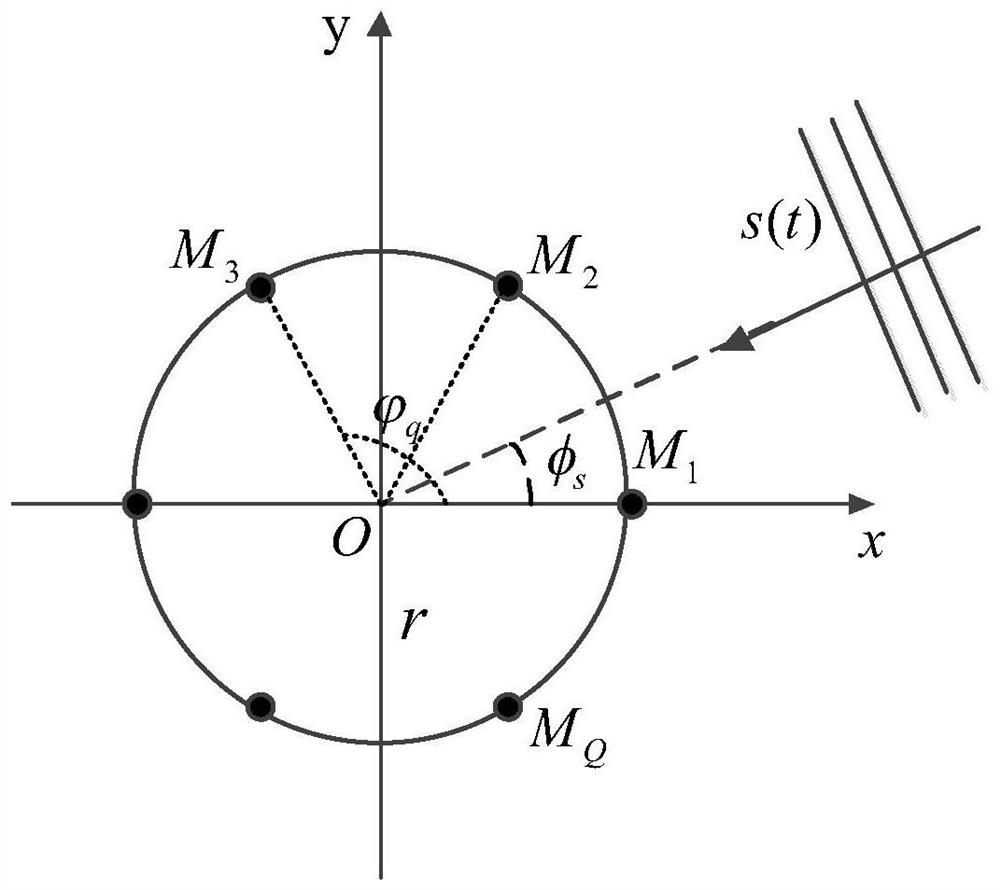
[0061] Step 1: Arranging Q identical omnidirectional microphones at equal intervals to form a circular microphone array with a radius of r;

[0062] Create a circular microphone array model, such as figure 1 As shown, there are Q omnidirectional microphones M 1 ,...,M Q Composition, the center of the array is selected as the coordinate origin O, the microphones are arranged counterclockwise and equally spaced on a circle with a rad...


PUM


Abstract

The invention discloses a time-frequency-space joint weighted circular harmonic domain pseudo-sound intensity sound source positioning method. In the method, the previously designed six-element circular microphone array is used to collect voice signals; considering that the voice signal has short-term Steady characteristics, transform the collected voice signal into the time-frequency domain, use the time-frequency domain PHAT weighting for filtering processing, reduce the impact of noise and reverberation on positioning performance; use the normalized zero-order eigenbeam and first-order eigenbeam , and use the time-frequency domain PHAT weighted circular harmonic pseudo-sound intensity sound source localization method to roughly estimate the angle; use the rough estimated angle to construct the spatial beam directivity function, and obtain the normalized time-frequency domain PHAT weighted joint directivity weighted zero-order Eigenbeam, and then use the time-frequency-space domain joint weighted circular harmonic domain pseudo-sound intensity method to solve the problem to obtain accurate sound source estimation angle.

Description

technical field [0001] The invention relates to the technical field of sound source localization, in particular to a sound source localization method of pseudo-sound intensity in the circular harmonic domain with joint weighting of time-frequency-space domain. Background technique [0002] In audio and speech signal processing, sound source localization technology using microphone arrays is an important research direction. Linear microphone arrays have been widely used in sound source localization because of their simplicity and easy understanding, such as sonar (see Literature: Wang Yan, Zou Nan, Liang Guolong. Near-field active correction method for hydrophone array position in strong multi-path environment [J]. Acta Physica Sinica, 2015, 64(2): 024304 1-10), video conference call (see Literature: Barbara Rauch, FriedrichFaubel, Dietrich Klakow.An analysis of nonstationary variance estimates in the maximum negentropy beamformer[C].Joint Workshop on Hands-free SpeechCommuni...

Claims


Application Information

Patent Timeline
Patent Type & Authority Patents(China)
IPC IPC(8): G01S5/22
CPCG01S5/22
Inventor 宋宫琨琨陈华伟吕中兴张普芬
Owner NANJING UNIV OF AERONAUTICS & ASTRONAUTICS
Why Eureka
Try Eureka