
Method for determining the state of loading of a particle filter and internal combustion engine

A particulate filter, load state technology, applied in the direction of internal combustion piston engine, combustion engine, machine/engine, etc., can solve the problems of pressure drop, compressor pressure ratio drop, turbine power drop, etc., and achieve the effect of cost saving

Active Publication Date: 2018-09-18
VOLKSWAGEN AG
View PDF12 Cites 0 Cited by
  • Summary
  • Abstract
  • Description
  • Claims
  • Application Information

AI Technical Summary

Problems solved by technology

In the case of an internal combustion engine with an exhaust gas turbocharger, the increase in the exhaust backpressure due to the carbon particles trapped in the particulate filter results in the following, namely, the pressure drop across the turbine of the exhaust gas turbocharger (Druckgefälle ) and thus possible turbine power drop
Since the turbine and compressor of the exhaust gas turbocharger are mechanically coupled, the possible compressor pressure ratio is also reduced

Method used

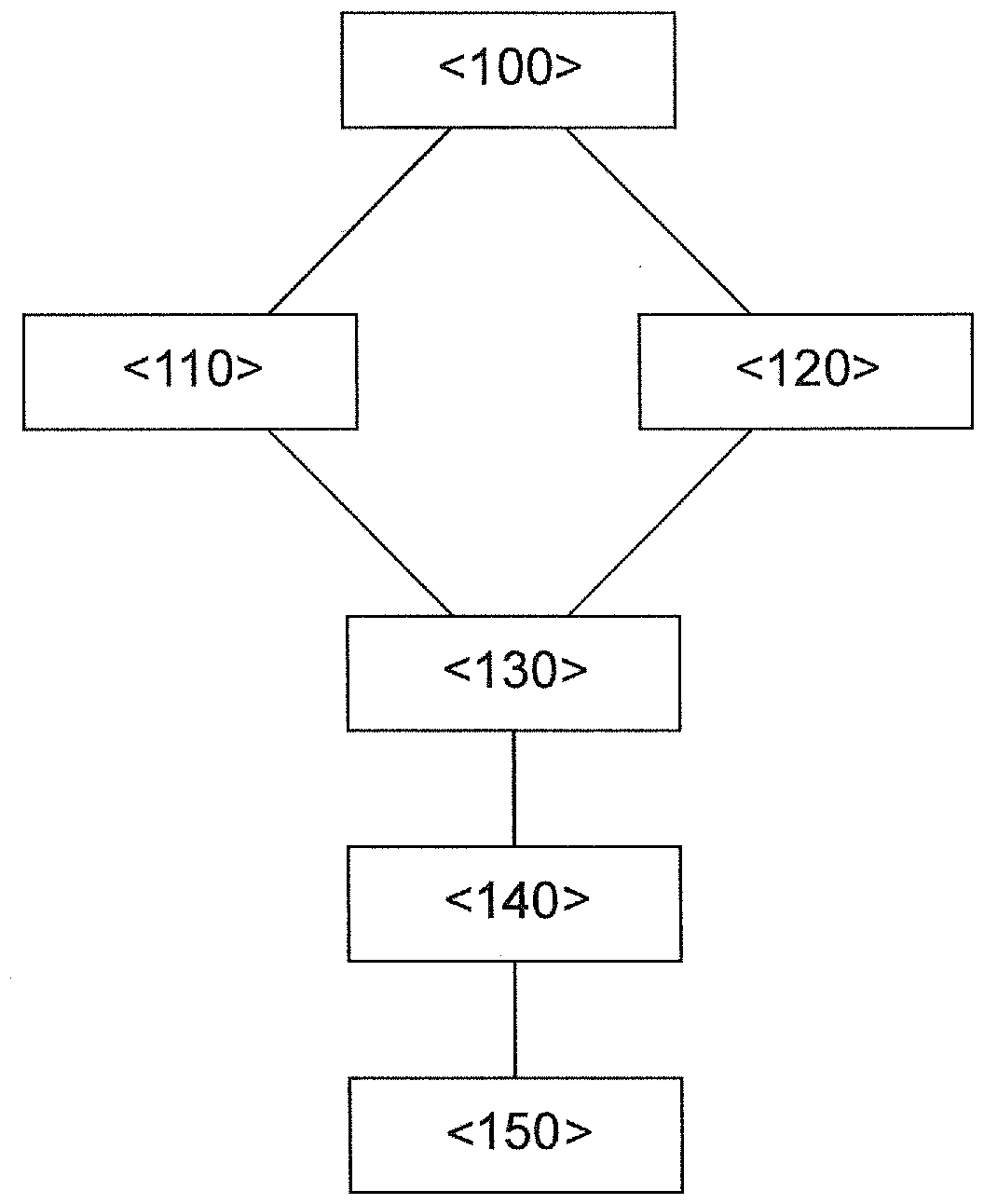

Image

  • Method for determining the state of loading of a particle filter and internal combustion engine
  • Method for determining the state of loading of a particle filter and internal combustion engine

Examples


Embodiment Construction

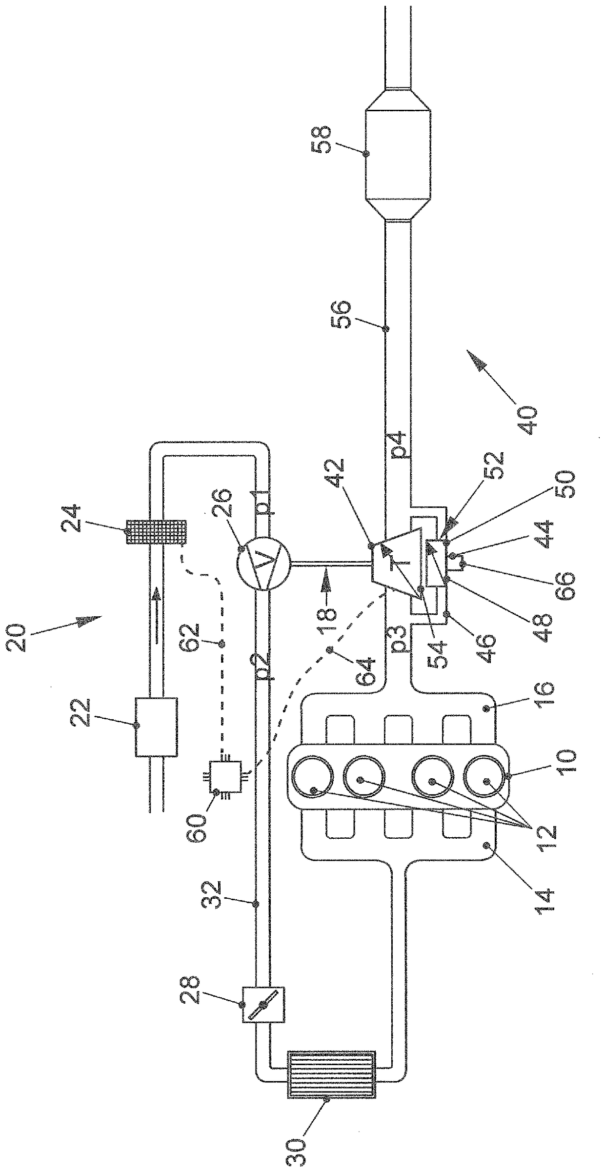
[0053] figure 1 An internal combustion engine 10 for a motor vehicle is shown. The internal combustion engine 10 has a combustion chamber 12 in which a fuel-air mixture is combusted. Internal combustion engine 10 is coupled via inlet 14 to an air supply system 20 of internal combustion engine 10 . The air supply system 20 comprises an air filter 22 in the flow direction of fresh air through a fresh line 32 of the air supply system 20 and an air mass meter 24 , preferably a hot-film air mass meter, downstream of the air filter 22 . Downstream of the air mass meter 24 , a compressor 26 of the exhaust gas turbocharger 18 is arranged in the fresh air line, with which compressor 26 fresh air is compressed for better filling of the combustion chamber 12 . A throttle plate 28 for controlling the amount of air supplied to the combustion chamber is arranged downstream of the compressor 26 . In addition, a charge air cooler 30 is arranged downstream in the fresh air line 32 between t...


PUM


Abstract

A method for determining the state of loading of a particle filter in an exhaust system of an internal combustion engine turbocharged by an exhaust turbocharger is provided. To determine the state ofloading, a position of a control mechanism of the turbine of the exhaust turbocharger is detected and compared with the position during operation of the internal combustion engine with the same operating parameters with the particle filter unladen. In addition, an air mass meter is provided at upstream of the internal combustion engine in order to be able to distinguish a change in the pressure situation at the turbine of the exhaust turbocharger due to a rise in the exhaust gas backpressure owing to increasing loading of the particle filter from a change in the pressure situation owing to leakage of the air supply system. An internal combustion engine having a control unit which is configured to carry out such a method is also provided.

Description

technical field [0001] The invention relates to a method for determining the loading state of a particle filter in an exhaust system of an internal combustion engine and to an internal combustion engine with an exhaust gas turbocharger and a particle filter arranged in the exhaust system. Background technique [0002] Current and future exhaust gas regulations (Abgasgesetzgebung), which will become more stringent, place high demands on raw engine emissions (Rohemission, sometimes also called untreated emissions) and exhaust gas aftertreatment of internal combustion engines. In the case of diesel engines, particulate filters for suppressing the formation of carbon particles (Russpartikel) in the case of engine combustion have been standard for many years and are currently used in almost all diesel engines for exhaust gas aftertreatment . With the introduction of the exhaust gas standard EU6 for gasoline engines (Ottomotor, sometimes also called Otto engines), limit values ​​...

Claims


Application Information

Patent Timeline
IPC IPC(8): F01N9/00F01N11/00F02M26/15F02M26/06F02D9/04
CPCF01N9/00F01N11/00F02D9/04F02M26/06F02M26/15F01N3/021F01N9/002F01N2260/04F01N2550/02F01N2560/07F01N2560/08F01N2900/08F01N2900/1406F01N2900/1606F02B37/183F02B37/24F02B2037/122F02D41/0007F02D2200/0812F02M35/10386Y02T10/12Y02T10/40F01N5/00F01N2550/04
Inventor M.曼多施
Owner VOLKSWAGEN AG
Learn More