Simulation method and system for twelve-phase brushless direct current motor
A brushed DC motor and simulation method technology, applied in the field of simulation, can solve the problems that the performance can not meet the needs, the motor control is complex, and can not be achieved.
- Summary
- Abstract
- Description
- Claims
- Application Information
AI Technical Summary
Problems solved by technology
Method used
Image
Examples
Embodiment 1
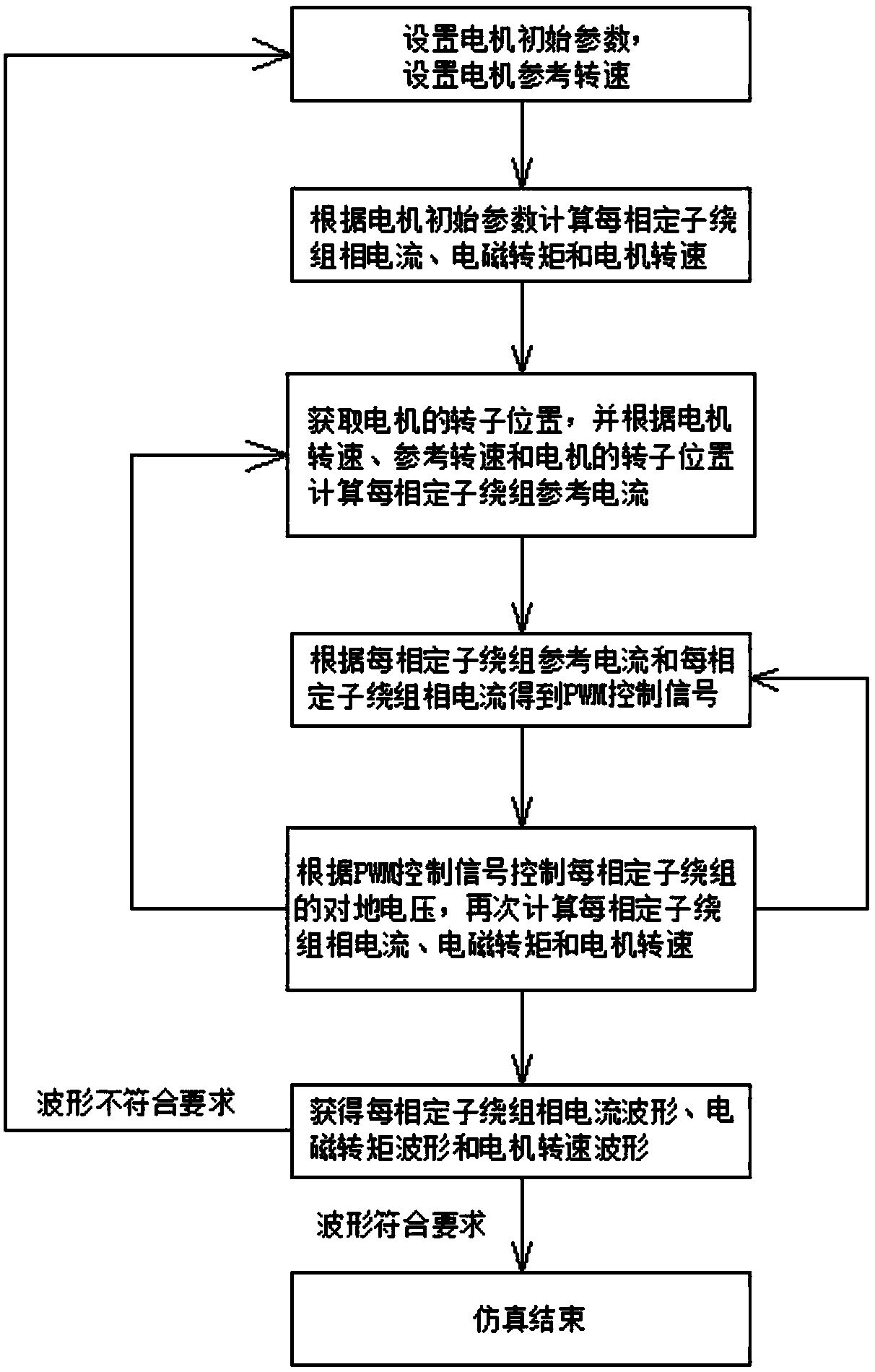
[0065] like figure 1 As shown, this embodiment provides a twelve-phase brushless DC motor simulation method, which is applied to simulation software, including:
[0066] Step S1: Set the initial parameters of the motor, and set the reference speed of the motor;
[0067] Step S2: Calculate the phase current, electromagnetic torque and motor speed of each phase of the stator winding according to the initial parameters of the motor;
[0068] Step S3: Obtain the rotor position of the motor, and calculate the stator winding reference current of each phase according to the motor speed, the reference speed and the rotor position of the motor;
[0069] Step S4: Obtain the PWM control signal according to the reference current of the stator winding of each phase and the phase current of the stator winding of each phase;
[0070] Step S5: Control the ground voltage of each phase stator winding according to the PWM control signal, calculate the phase current, electromagnetic torque and ...
Embodiment 2
[0115] like Figure 7 As shown, this embodiment provides a twelve-phase brushless DC motor simulation system, which can be simulated by the simulation method provided in Embodiment 1, including:
[0116] Motor main module: used to calculate the motor stator winding phase current, electromagnetic torque and motor speed according to the motor parameters, and connect with the reference current controller module and the current hysteresis controller module respectively through the position detection module and the current detection module. It is used to feed back the motor speed to the reference current controller module, and is also used to transmit the stator winding phase current, electromagnetic torque and motor speed to the oscilloscope module, wherein the position detection module is used to transmit the obtained motor rotor position to the reference The current controller module, the current detection module is used to transmit the acquired phase current of each phase of th...
Embodiment 3
[0131] This embodiment further describes the modules involved in Embodiment 2 in conjunction with specific packaging forms in the simulation software.
[0132] like Figure 8 As shown, it is a simulation schematic diagram of the main module of the motor. The main module includes a motor body module, a torque measurement module and a speed measurement module. and i3abc represent); torque measurement module: used to calculate the electromagnetic torque of the motor (represented by Te in the figure); speed measurement module: used to calculate the angular velocity of the motor (represented by n in the figure); in addition, TL is Load torque, ua, ub, uc, ua1, ub1, uc1, ua2, ub2, uc2, ua3, ub3 and uc3 are the twelve-phase stator winding voltage to ground respectively, Pos is the position of the rotor, eabc, e1abc, e2abc and e3abc are the counter electromotive force of the twelve-phase stator windings.
[0133] like Figure 9 As shown, taking the stator winding I as an example, t...
PUM
 Abstract
Description
Claims
Application Information
 - R&D
- Intellectual Property
- Life Sciences
- Materials
- Tech Scout
- Unparalleled Data Quality
- Higher Quality Content
- 60% Fewer Hallucinations
Browse by: Latest US Patents, China's latest patents, Technical Efficacy Thesaurus, Application Domain, Technology Topic, Popular Technical Reports.
© 2025 PatSnap. All rights reserved.Legal|Privacy policy|Modern Slavery Act Transparency Statement|Sitemap|About US| Contact US: help@patsnap.com


