
Protective cover, connector, disassembling tool and method of disassembling protective cover on connector

A technology for disassembling tools and protective covers, which is applied in the assembly/disassembly, connection, and parts of connecting devices of contacts, etc., can solve the problem of high cost of connectors, avoid poor contact, achieve protection or expansion, The effect of easy disassembly

Active Publication Date: 2018-09-14
FENGHUO COMM SCI & TECH CO LTD
View PDF7 Cites 1 Cited by
  • Summary
  • Abstract
  • Description
  • Claims
  • Application Information

AI Technical Summary

Problems solved by technology

If a replacement card with a connector is used, the cost of the connector remains high

Method used


Image

  • Protective cover, connector, disassembling tool and method of disassembling protective cover on connector
  • Protective cover, connector, disassembling tool and method of disassembling protective cover on connector
  • Protective cover, connector, disassembling tool and method of disassembling protective cover on connector

Examples


Embodiment 1

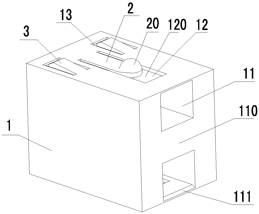
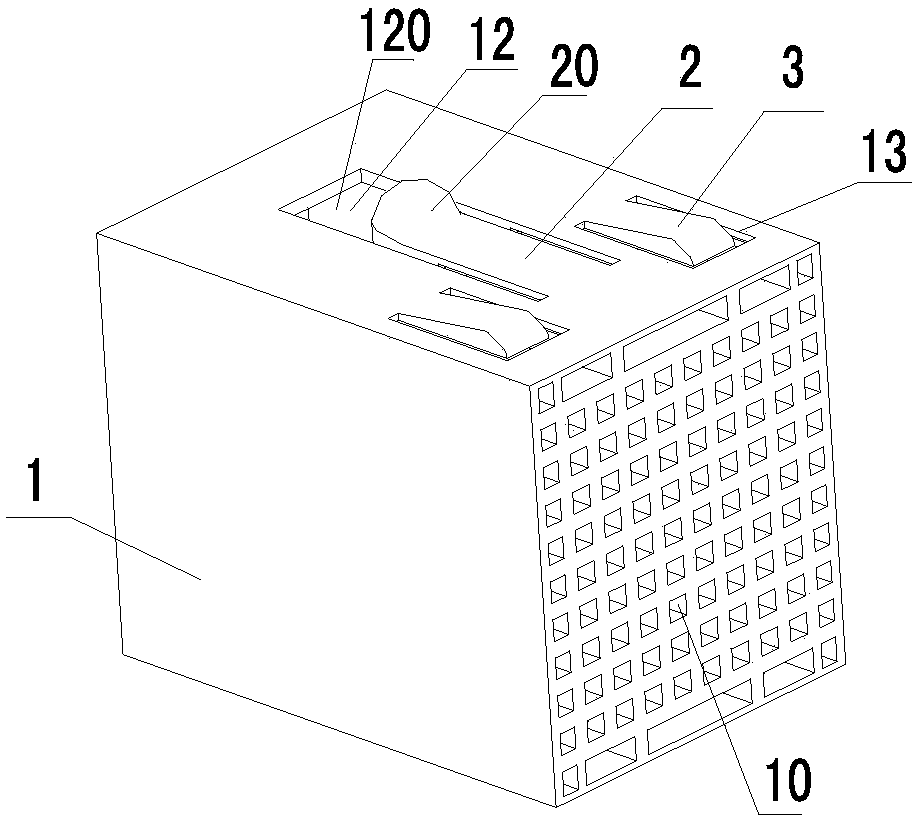
[0041] see figure 1 with figure 2 As shown, the embodiment of the present invention provides a protective cover for the protection of the connector 5, which includes a body 1, one end of the body 1 is concave and forms a cavity 10 for receiving the contact pin of the connector 5, the cavity 10 Can be a large space, or can be such as figure 2 The small spaces arranged in an array as shown in , protect the contact pins from being damaged by foreign objects and cause the needles to be reversed when the card is inserted and pulled out. The other end of the body 1 is concave and forms a connecting hole 11 for docking. The connecting hole 11 and The chamber 10 is not connected to avoid contamination of the contact pins by dust, etc., which can prevent the contact pins of the connector 5 from dust, avoid poor contact or affect the SI performance of the signal, and can also protect the contact pins from moisture and water. Poor contact is caused; the surface of the main body 1 is ...

Embodiment 2

[0044] see figure 1 with figure 2 As shown, the embodiment of the present invention provides a protective cover. The difference between this embodiment and Embodiment 1 is that the protective cover also includes an elastic pressing piece 2, which is located at the bayonet 12, one end of which is connected to the body 1 and The other end is a free end; the free end of the elastic pressing piece 2 protrudes from the outer surface of the body 1 . As shown in the figure, the free end is located close to the bayonet 12 .

[0045] If a protective cover is installed on the connector, since the adjacent slots of the plug-in device may be equipped with plug-in cards and the slot spacing is small and the slot depth is large, the power cannot be cut off and other services cannot be affected when the device is expanded, and it is generally impossible to operate with bare hands. , At this time, it is necessary to use a disassembly tool with a hook to disassemble the protective cover. In...

Embodiment 3

[0048] see figure 1 with figure 2As shown, the embodiment of the present invention provides a protective cover. The difference between this embodiment and Embodiment 2 is that the end of the bayonet 12 close to the connection hole 11 and the free end of the elastic pressing piece 2 are spaced apart from each other and form a locking area. 120. The advantage of such setting is that the hook of the disassembly tool is conveniently snapped on the bayonet 12, avoiding decoupling during the disassembly process, ensuring that the disassembly work can be completed at one time, and the work efficiency is improved.


PUM


Abstract

The invention discloses a protective cover, a connector, a disassembling tool and a method of disassembling the protective cover on the connector. The protective cover is used for protecting the connector, and comprises a body; one end of the body is concave and forms a cavity for accommodating a contact pin of the connector, the other end is concave and forms a connection hole for butt joint, andthe connection hole is not communicated with the cavity; and the surface of the body is provided with a bayonet communicated with the connection hole. According to the protective cover disclosed in the invention, the structure is simple, cyclic utilization is realized, the cost is saved, the contact pin of the connector is accommodated through opening the cavity, the contact pin is protected frombeing touched by a foreign body and from being damaged, pin inverting when an inserting card is inserted and pulled can be avoided, as the connection hole not communicated with the cavity is arranged, dust and the like can be prevented from polluting the contact pin, a dustproof role is played to the contact pin of the connector, bad contact or influenced signal SI performance can be avoided, moisture-proof and waterproof protection can be realized, and the contact pin can be prevented from being in bad contact due to corrosion.

Description

technical field [0001] The invention relates to the technical field of communication equipment, in particular to a protective cover, a connector, a removal tool and a method for removing a protective cover on a connector. Background technique [0002] With the increasing capacity of information electronic equipment, the equipment generally adopts card insertion mode, and there are many slots, which can realize flexible configuration and expansion of services. At the same time, due to the increasing capacity, the speed of the equipment and the connection density between the backplane and the card are also getting higher and higher, and the reliability requirements for the connection between the card and the backplane connector are getting higher and higher. On the one hand, the contact pins of the connector are getting thinner and thinner, and it is easy to be damaged by foreign objects during the production process, causing the pins to be reversed when the card is inserted a...

Claims


Application Information

Patent Timeline
Patent Type & Authority Applications(China)
IPC IPC(8): H01R12/71H01R13/46H01R13/52H01R43/20
CPCH01R12/716H01R13/46H01R13/52H01R13/5213H01R43/20
Inventor 游汉涛
Owner FENGHUO COMM SCI & TECH CO LTD
Learn More