Three-point cylindricity measuring device and cylindricity error separating method based on V-shaped block

A technology for measuring devices and cylindricity, which is applied in the direction of measuring devices, instruments, etc., to achieve the effect of improving the accuracy of in-situ measurement

Active Publication Date: 2018-09-14
HEFEI UNIV OF TECH
View PDF5 Cites 2 Cited by
  • Summary
  • Abstract
  • Description
  • Claims
  • Application Information

AI Technical Summary

Problems solved by technology

[0004] The present invention is to avoid the problems existing in the above-mentioned prior art, and provides a three-point cylindricity measurement device and a cylindricity error separation method based on a V block, so as to solve the problem of in-situ precision measurement and reconstruction of a large cylindrical profile; In the original system, the influence of the error motion of the shaft system and guide rail on the measurement of the cylindrical profile, overcome the first-order harmonic suppression of the three-point roundness EST, and realize the full harmonic extraction of the profile of each measurement section of the measured cylinder during the measurement process, ensuring that the cylindrical High accuracy of profile measurement and reconstruction, reducing the cost of in-situ measurement of large cylindrical profiles

Method used


Image

  • Three-point cylindricity measuring device and cylindricity error separating method based on V-shaped block
  • Three-point cylindricity measuring device and cylindricity error separating method based on V-shaped block
  • Three-point cylindricity measuring device and cylindricity error separating method based on V-shaped block

Examples


Embodiment Construction

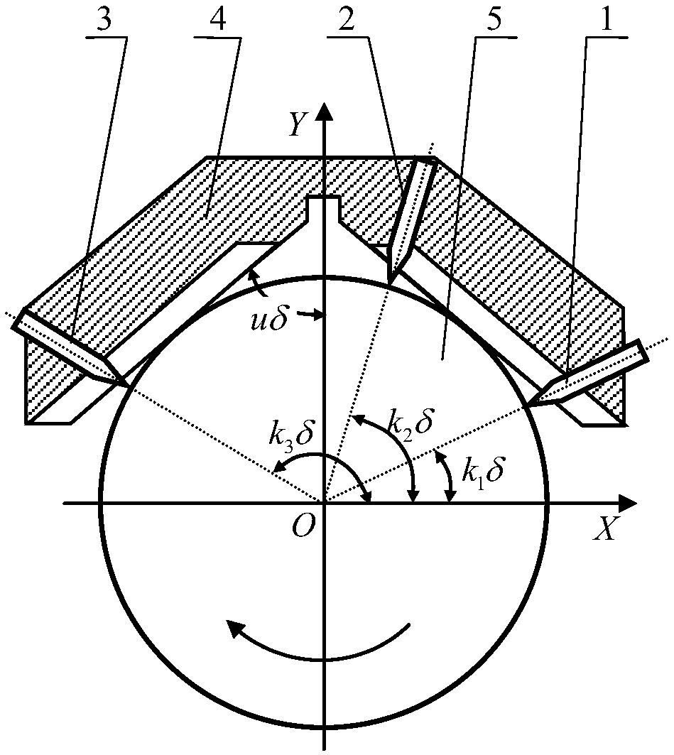
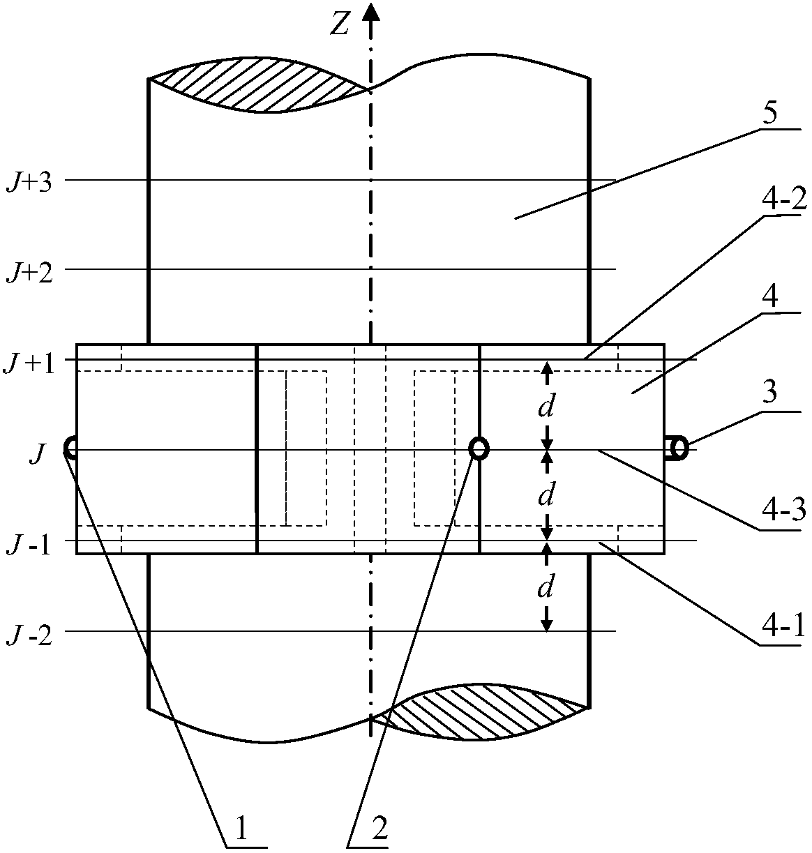
[0049] see figure 1 and figure 2 , the structural form of the three-point cylindricity measuring device based on the V block in the present embodiment is:

[0050] The cylindricity measurement refers to the cylindricity measurement of the cylindrical measured body 5; the measuring device uses the outer cylindrical surface of the measured body 5 along the axial direction as the guide rail, and the V block 4 as the axial sliding measuring frame. The block is provided with a sensor, and the sliding measuring frame is supported on the outer cylindrical surface of the measured body 5 by the V-shaped surface of the V block, and the V block is used to move axially at a set interval to obtain the corresponding measured value for the measured body 5. Position; in the position measurement, the measured body 5 is driven to rotate a circle in its slewing support shaft system, the V block keeps the circumferential position unchanged, and keeps its V-shaped surface in contact with the out...


PUM


Abstract

The invention discloses a three-point cylindricity measuring device and a cylindricity error separating method based on a V-shaped block, which are used for measuring the cylindricity of a cylindricalmeasured object. The device is characterized in that the measured object takes an outer cylindrical surface in the axial direction as guide rails, and the V-shaped block is used as an axial sliding measurement rack; sensors are arranged on the V-shaped block; the sliding measurement rack is supported by the outer cylindrical surface of the measured object by using V-shaped surfaces of the V-shaped block; the V-shaped block moves according to the axial direction of set intervals to obtain corresponding measurement positions of the measured object; on the measurement positions, the measured object is driven by a rotary supporting shaft system of the measured object to rotate for one circle, the circumferential position of the V-shaped is kept unchanged, and the V-shaped surface of the V-shaped block is kept in contact with the outer cylindrical surface of the measured object. The three-point cylindricity measuring device and the cylindricity error separating method disclosed by the invention are especially applied to cylindrical profile measurement reconstruction; portable large-sized cylindrical profile in-situ measurement can be realized; the measurement is irrelevant to an in-situ rotary supporting shaft system and in-situ guide rails, and full-harmonic separation of all error motions in the measurement process is realized at the minimum quantity of sensors, so that high precision of cylindrical profile measurement reconstruction is ensured.

Description

technical field [0001] The present invention relates to precision testing technology and the field of design, manufacture and use of large-scale manufacturing equipment, more specifically to a three-point cylindricity measurement device based on a V block, a method for separating cylindricity errors, and its reconstruction in cylindrical profile measurement in the application. Background technique [0002] Shaft rolls are an important large-scale component in the large-scale equipment manufacturing industry. In the production equipment of large-scale solar panels, LCD screens, automotive steel plates, high-quality paper and industrial composite panels, large-scale shaft rollers are the core components of the equipment, and the cylindricity error is a sign of the accuracy of the shaft-roll profile. During the production process of the product, the profile error of the shaft and roll, including the cylindricity error, etc., will be copied to the product surface, causing vario...

Claims


Application Information

Patent Timeline
IPC IPC(8): G01B21/20
CPCG01B21/20
Inventor 刘文文付俊森王宏涛
Owner HEFEI UNIV OF TECH
Why Eureka
Try Eureka