Feeding system of automatic production line

An automatic production line and feeding system technology, applied in metal processing equipment, feeding devices, manufacturing tools, etc., can solve the problems of low stamping efficiency, long time consumption, and not grabbing multiple pieces together, so as to reduce power The setting of the mechanism, the effect of improving the feeding efficiency and shortening the feeding time

Inactive Publication Date: 2018-09-14
宁波高新区神台德机械设备有限公司
View PDF0 Cites 0 Cited by
  • Summary
  • Abstract
  • Description
  • Claims
  • Application Information

AI Technical Summary

Problems solved by technology

In this process, the loading of each plate needs to go through 4 operation steps, and in order to facilitate the processing of the plates, the plates are placed separately one by one, which means that the manipulator is grabbing the plate. Sometimes it is also necessary to operate each plate separately instead of grabbing multiple pieces together, and because the 4 steps of loading are all completed by the same manipulator, therefore, during this period, the remaining plates will not If there is any operation, this period of operation time will be idle. In this way, the entire loading process takes a long time, but the efficiency is not high, resulting in low stamping efficiency of the plate

Method used


Image

  • Feeding system of automatic production line
  • Feeding system of automatic production line

Examples


Embodiment Construction

[0022] Further detailed explanation through specific implementation mode below:

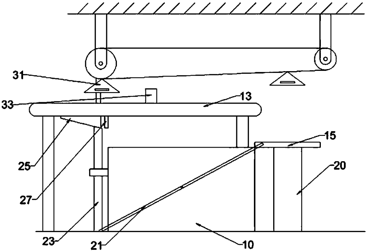
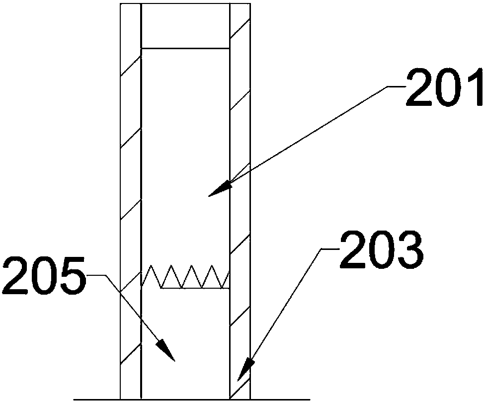
[0023] The reference numerals in the accompanying drawings of the description include: placement box 10, conveyor belt 13, push plate 15, sleeve 20, inner cylinder 201, rotating shaft 205, outer cylinder 203, first connecting rod 21, second connecting rod 23, The third connecting rod 25, the push block 27, the grab material 31, and the shift block 33.

[0024] Such as figure 1 The feeding system of the shown automated production line includes a placement box 10 for placing panels and a conveyor belt 13 for transporting panels. The conveyor belt 13 includes a frame, wherein: the placement box 10 is located below the conveyor belt 13 frame, and the bottom surface of the placement box 10 A supporting mechanism that can push the plate upwards is provided on the top, and a pushing mechanism is arranged in front of the feeding end of the conveyor belt 13. The pushing mechanism includes a rotatable sha...


PUM


Abstract

The invention relates to the field of automatic material receiving and feeding devices, in particular to a feeding system of an automatic production line. The feeding system of the automatic production line comprises a placement box and a conveying belt, wherein plates are placed in the placement box; the conveying belt conveys the plates and comprises a rack; the placement box is provided with asupporting mechanism capable of pushing the plates to move upwards; a pushing mechanism is arranged in front of a feeding end of the conveying belt and comprises a rotating shaft capable of rotating,a sleeve and a pushing plate; the lower end of the sleeve is connected with the rotating shaft; the upper end of the sleeve is connected with the pushing plate; the rotating shaft can drive the sleeveto move vertically; the sleeve is connected with a push block through a connecting mechanism; the push block is positioned on the side, which is away from the pushing mechanism, of the placement box;the push block is slidably connected to the lower surface of the rack; when the sleeve moves upwards, the connecting mechanism pulls the push block to move away from the pushing plate; when the sleeve moves downwards, the connecting mechanism pushes the push block to move towards the pushing plate; a grabbing mechanism is arranged above the pushing mechanism and comprises a driving belt and a grabbing piece; and the grabbing piece can make contact with the pushing plate and can grab the plates on the pushing plate.

Description

technical field [0001] The invention relates to the field of automatic feeding and feeding devices, in particular to a feeding system of an automatic production line. Background technique [0002] Stamping is a forming processing method that applies external force to plates, strips, pipes and profiles by presses and molds to cause plastic deformation or separation, thereby obtaining workpieces of required shape and size. As an important processing method of mechanical manufacturing, metal stamping processing has been widely used in the production of automobile bodies, chassis, container shells, and iron core silicon steel sheets of electrical appliances. The original stamping production line mostly uses manual feeding to feed materials. With the development of technology, there are now many stamping production lines that can automatically load and unload materials. The feeding of the plate replaces the traditional manual feeding method, which improves the feeding efficiency...

Claims


Application Information

Patent Timeline
Patent Type & Authority Applications(China)
IPC IPC(8): B21D43/02B21D43/11B21D43/12
CPCB21D43/026B21D43/105B21D43/11B21D43/12
Inventor 陆世勇
Owner 宁波高新区神台德机械设备有限公司
Why Eureka
Try Eureka