
Device for processing backlight plate

A technology of backlight plate and air blowing device, which is applied in optics, nonlinear optics, instruments, etc., to achieve the effect of ensuring the speed of unloading

Pending Publication Date: 2018-09-11
重庆雄富光电科技有限公司
View PDF7 Cites 1 Cited by
  • Summary
  • Abstract
  • Description
  • Claims
  • Application Information

AI Technical Summary

Problems solved by technology

[0006] The object of the present invention is to provide a device for backlight processing, which solves the problem of manually turning the backlight in a clockwise or counterclockwise direction in the prior art.

Method used


Image

  • Device for processing backlight plate
  • Device for processing backlight plate
  • Device for processing backlight plate

Examples


Embodiment Construction

[0032] The present invention will be further described in detail below through specific implementations:

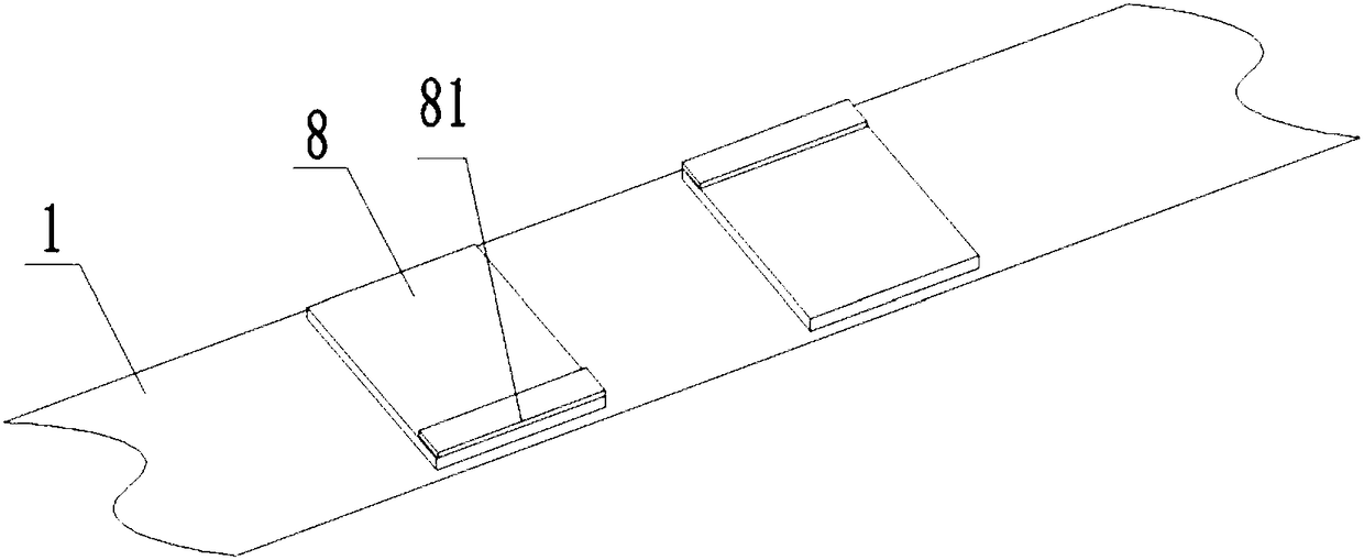
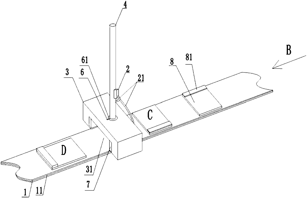
[0033] The reference signs in the drawings of the specification include: conveyor belt 1, rubber layer 11, blowing device 2, hose 21, clamping portion 3, groove 31, baffle plate 311, arc groove 32, placement cavity 321, first The trachea 33, the second trachea 34, the connecting rod 4, the connecting rod body 41, the turntable 42, the convex bar 421, the cavity 422, the first air hole 4221, the second air hole 4222, the air outlet 4223, the air blowing tube 5, the tube body 51, The branch tube 52, the identification strip 6, the pointer 61, the airbag 7, the pressure relief tube 71, the backlight plate 8, and the light bar 81.

[0034] The embodiment is basically as attached figure 1 , figure 2 , image 3 , Figure 4 , Figure 5 with Image 6 Shown:

[0035] The backlight processing device includes a conveyor belt 1, an air blowing device 2, and a clamping part 3. The clampin...


PUM


Abstract

The invention relates to the technical field of backlight plate processing, in particular to a device for processing backlight plate, which comprises a conveying belt, an air blowing device and a clamping part, wherein the clamping part is arranged above the conveying belt, and the clamping part is rotatably connected with a connecting rod; the lower part of the clamping part is provided with a groove, and the inner walls of both sides of the groove are fixedly provided with an air bag; a pressure relief pipe is arranged on each air bag; the connecting rod comprises a connecting rod body and aturntable arranged at the lower end of the connecting rod; a rotating cavity is arranged in the clamping part, the turntable is rotatably connected in the rotating cavity, and a convex strip is fixedly arranged on the turntable; the outer periphery of the rotating cavity is provided with an arc-shaped groove, both ends of the arc-shaped groove are communicated with a placing cavity; and the arc-shaped groove is used for limiting the turntable; a cavity is arranged in the turntable, and a first air hole and a second air hole are arranged on the cavity wall of the cavity; a first air pipe and asecond air pipe communicated with the rotating cavity are arranged in the clamping part; the bottom of the cavity is provided with an air outlet; the clamping part is internally provided with an airblowing pipe, and the air blowing pipe is communicated with the air outlet hole. According to the scheme, the problem of manually changing the placing state of the backlight plate in the prior art issolved.

Description

Technical field [0001] The invention relates to the technical field of backlight plate processing, in particular to a device for backlight plate processing. Background technique [0002] The backlight board is a light source device used to ensure the light is emitted behind the LCD screen; the bottom layer of the backlight board is the backlight module, and the upper surfaces of both sides of the backlight module are pasted with black and white tape; the other layers are pasted on the backlight with black and white tape On the source module; then the light bar is welded or glued to the backlight board to complete the pre-production of the backlight board. In the prior art, the welding or pasting of the light bar of the backlight plate is manually completed, and after the manual completion, it is put on the conveyor belt and uploaded to the next process. [0003] The existing technology has the following problems: [0004] When placing the backlight board on the conveyor belt, the s...

Claims


Application Information

Patent Timeline
Patent Type & Authority Applications(China)
IPC IPC(8): G02F1/13
CPCG02F1/1303
Inventor 唐纯超
Owner 重庆雄富光电科技有限公司
Learn More