
Asynchronous positioning method based on single station dual frequency continuous wave radar

A positioning method, wave radar technology, applied in the field of dual-frequency continuous wave radar positioning, can solve problems such as large errors, and achieve the effect of low complexity and cost

Inactive Publication Date: 2018-09-11
UNIV OF ELECTRONICS SCI & TECH OF CHINA
View PDF15 Cites 7 Cited by
  • Summary
  • Abstract
  • Description
  • Claims
  • Application Information

AI Technical Summary

Problems solved by technology

[0004] The purpose of the present invention is that the existing dual-frequency continuous wave radar positioning algorithm is designed for the synchronous mode. Due to the phase disturbance caused by the movement of the moving target, it will cause a large error in the asynchronous mode. Asynchronous Mode Positioning Method Based on Radar Phase Compensation

Method used


Image

  • Asynchronous positioning method based on single station dual frequency continuous wave radar
  • Asynchronous positioning method based on single station dual frequency continuous wave radar
  • Asynchronous positioning method based on single station dual frequency continuous wave radar

Examples


Embodiment Construction

[0064] Below in conjunction with accompanying drawing and embodiment the present invention will be further described:

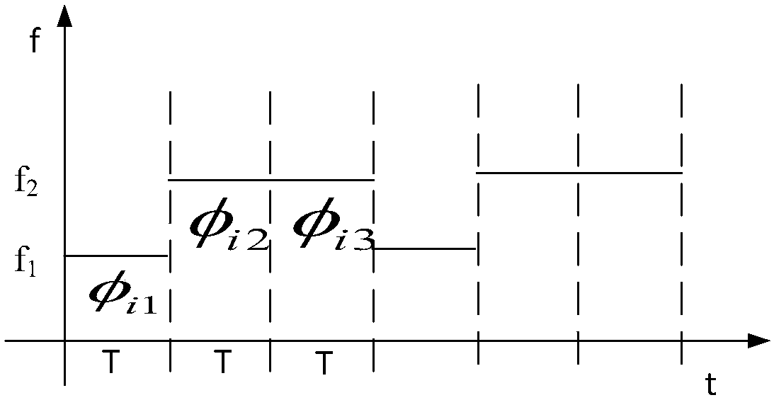
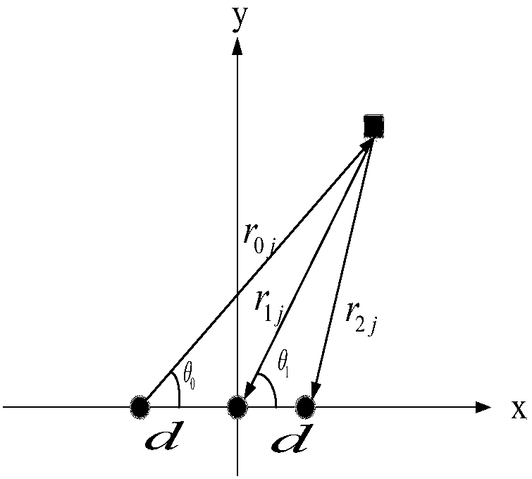
[0065] In order to illustrate the present invention more conveniently, as figure 2 As shown, the radar transmits continuous wave signals in three states, assuming the radar carrier frequency f 1 = 24Ghz, f 2 = 24.003Ghz, the duration of each state T = 45ms. Such as image 3 Shown is a linear array on a 2D plane. Such as Figure 4 As shown in , the estimated trajectory of the moving target has a speed of 3.7km / h, assuming that the position of the moving target is (0,25).

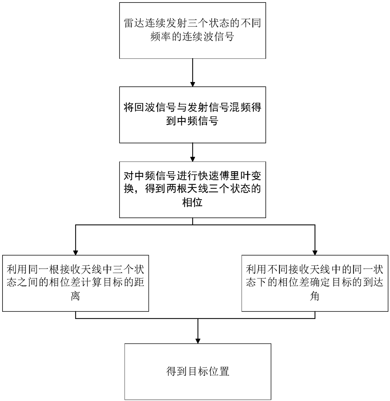
[0066] Step 1: The radar continuously transmits continuous wave signals of different frequencies in three states, and mixes the echo signal with the transmitted signal to obtain an intermediate frequency signal.

[0067] The emission signal in the first state is:

[0068] u t =cos(2πf 1 t)=cos(150.72×10 9 t) (1)

[0069] Then the echo signal of the target is:

[0070] u r =cos(...


PUM


Abstract

The invention belongs to the technical field of dual-frequency continuous wave radar positioning, and relates to an asynchronous positioning method based on single station dual frequency continuous wave radar. The method no longer transmits two continuous wave signals of different frequencies at the same time, but switches between three states to transmit two continuous wave singles of different frequencies, and the third state compensates for the phase disturbance caused by the target speed. Compared to the synchronous mode, this method has lower complexity and cost, and is suitable for mostcommercial products of short-range radars with a single oscillator structure. The simulation results show that the positioning accuracy of the method can reach the centimeter level.

Description

technical field [0001] The invention belongs to the technical field of dual-frequency continuous wave radar positioning, and relates to an asynchronous positioning method based on single-station dual-frequency continuous wave radar. Background technique [0002] Short-range non-contact microwave radar systems have been widely used in the monitoring of military, environmental, health and commercial systems. One of the important areas of short-range microwave / mm-wave radar is moving object detection, localization and tracking, which is a hot topic in security and surveillance applications. Target locations for short-range radar systems are estimated using several localization techniques by measuring range, angle of arrival (AOA), or hybrid parameters. In short-range radar, wideband radar and dual-frequency continuous wave (CW) are used for distance estimation. The former, such as frequency modulated wave (FMCW) radar, stepped frequency radar, and ultra-wideband radar, are ca...

Claims


Application Information

Patent Timeline
Patent Type & Authority Applications(China)
IPC IPC(8): G01S13/42
CPCG01S13/42
Inventor 黄际彦周贻能王义圆张曦文张彤彤王亚龙
Owner UNIV OF ELECTRONICS SCI & TECH OF CHINA
Learn More