Auto-centering control system having abrasion compensation
A control system, automatic centering technology, applied in electric controllers, controllers with specific characteristics, material analysis using sonic/ultrasonic/infrasonic waves, etc. and other problems, to achieve the optimal effect, the best stability and reliability, and the best comprehensive effect.
- Summary
- Abstract
- Description
- Claims
- Application Information
AI Technical Summary
Problems solved by technology
Method used
Image

Examples
Embodiment 1
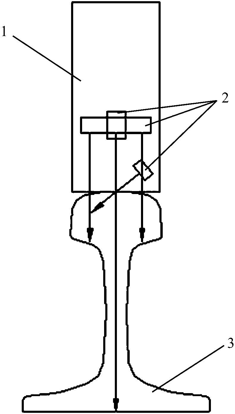
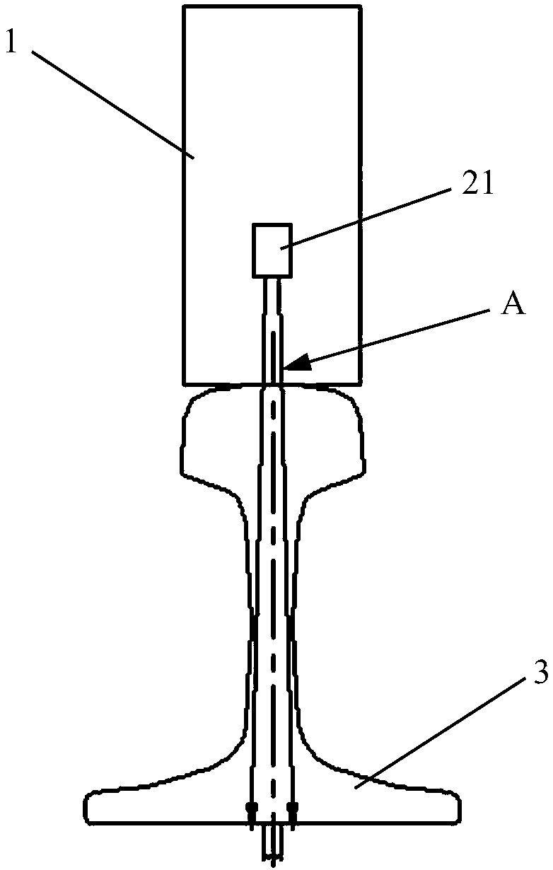
[0064] The technical solution of this embodiment is to analyze the contact situation between (ultrasonic) probe wheel 1 and rail 3, and to study the influence of rail head wear on ultrasonic incident, thereby proposing a method of using the rail head wear value to automatically control the centering reference. The compensation control system reduces the loss of bottom wave and improves the detection effect of flaw detection.
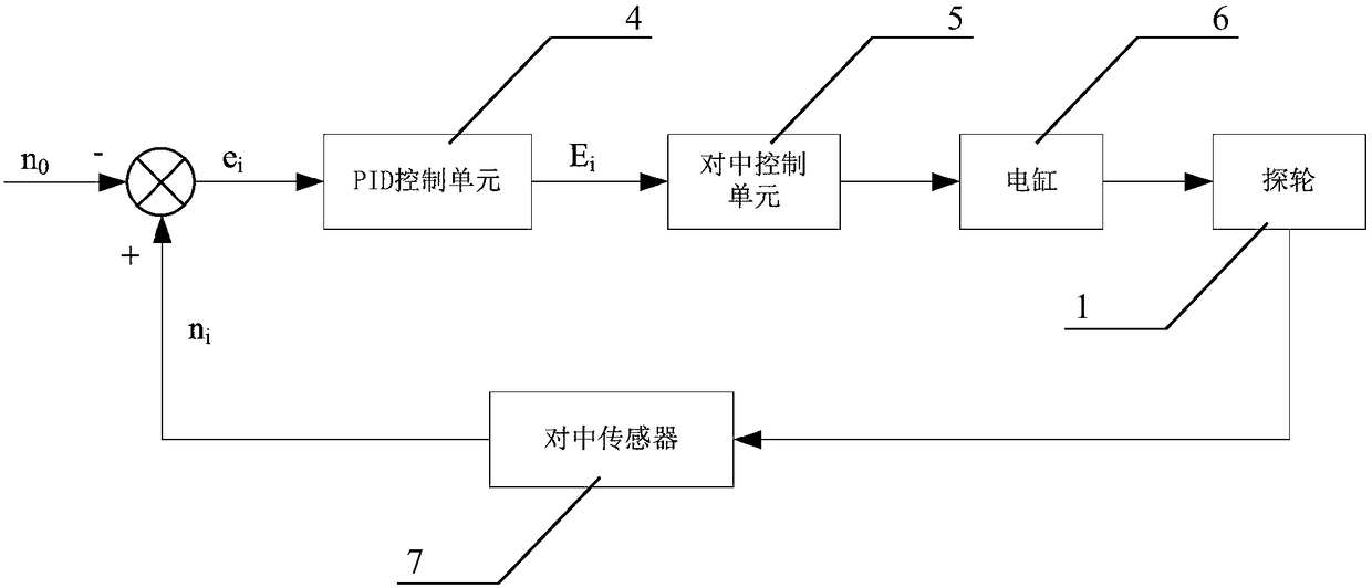
[0065] as attached Figure 10 As shown, an embodiment of the automatic centering control system 10 with wear compensation of the present invention specifically includes:
[0066] Centering the sensor 7 to obtain the rail profile data inside the rail 3 and the actual position of the probe wheel 1;
[0067] The wear compensation calculation unit 9 calculates the wear amount of the rail head of the rail 3 according to the rail profile data inside the rail 3, calculates the wear compensation amount based on the wear amount, and compensates the centering ref...
Embodiment 2
[0088] As described in Embodiment 1, when S adopts the third gear for compensation, wear compensation can be realized to a certain extent to achieve the purpose of the present invention. In this case, mild wear can be canceled on the basis of fourth gear compensation in this embodiment Compensation, but this will lead to a delay in the intervention time of the wear compensation mechanism, which may cause some mild wave loss. However, when S adopts the fourth gear or above, due to the increase of the compensation threshold, it may lead to frequent changes of the reference, which may have a certain degree of influence on the stability of the control. Therefore, in actual situations, the compensation effect is the best when S adopts the fourth gear, which combines high precision, high speed, high stability and reliability of wear compensation.
[0089] The technical solution of this embodiment will be introduced below by taking the fourth gear compensation with the best comprehen...
Embodiment 3
[0101] Regarding the calculation of rail head wear, Embodiment 1 and Embodiment 2 adopt the area calculation method, which is a method suitable for graphical rail profile calculation. Other calculation methods can also be implemented, such as calculating the slope of the profile line of the rail head in this embodiment.
[0102] as attached Figure 9 As shown, the wear compensation calculation unit 9 determines the wear amount of the rail head of the rail 3 by calculating the slope k of the actual profile line C1 inside the rail head of the rail 3 . According to the rail head slope method, if the centering reference set on the non-wearing rail 3 is n 0 (unit: mm), then the centering reference is set to n when there is wear 0 -m, where the value of m (unit: mm) is determined according to the range of k. In order to maintain the stability of the control, the range of k is set to the third gear and above.
[0103] When the range of k is set to the third gear, the wear compensa...
PUM
 Abstract
Description
Claims
Application Information
 - R&D
- Intellectual Property
- Life Sciences
- Materials
- Tech Scout
- Unparalleled Data Quality
- Higher Quality Content
- 60% Fewer Hallucinations
Browse by: Latest US Patents, China's latest patents, Technical Efficacy Thesaurus, Application Domain, Technology Topic, Popular Technical Reports.
© 2025 PatSnap. All rights reserved.Legal|Privacy policy|Modern Slavery Act Transparency Statement|Sitemap|About US| Contact US: help@patsnap.com