


Quick Research
Generate reliable direction feasibility study reports for your R&D in just a few steps.

Technical Q&A
Discover and master advanced knowledge NOW. Basics, ideas, possibilities, all at once.

Find Solutions
As an expert in R&D theories, this can generate solutions to your technical problems instantly.

Evaluate Feasibility
Analyze your overall solution with one click, know your potential R&D risks in advance.

Monitor Landscape
Get weekly tech updates, stay abreast of the latest tech innovations and key insights.
A wind turbine control method and system
A technology of wind turbines and control methods, applied in the direction of wind engine control, engine control, control algorithm types, etc., can solve the problems of ignoring the aerodynamic load of wind turbines and high mechanical loss of wind turbines, and achieve small aerodynamic loads, stable output power, The effect of reducing mechanical loss
- Summary
- Abstract
- Description
- Claims
- Application Information
AI Technical Summary
Problems solved by technology
Method used
Image

Examples
Embodiment 1
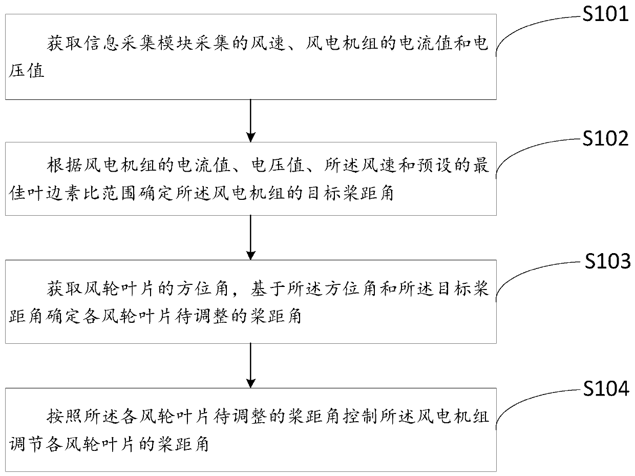
[0053] Embodiment one: if figure 1 As shown in the flow chart of a control method for a wind turbine, an embodiment of the present invention provides a control method for a wind turbine, which is applied to a cooperative controller of a wind turbine in a microgrid. The acquisition module is connected to the wind turbine blades of the wind turbine, and the microgrid operation mode is divided into a grid-connected operation mode and an isolated operation mode. The grid-connected operation mode usually adopts a fixed-pitch control strategy in order to obtain the maximum wind energy. The control strategy during grid-connected operation is optimized, and when the microgrid operates in grid-connected mode, the method includes the following steps:
[0054] Step S101, obtaining the wind speed, the current value and the voltage value of the wind turbine collected by the information collection module;
[0055] In the embodiment of the present invention, the wind turbine may include: a ...
Embodiment 2
[0087] Embodiment two: if Figure 4 The shown is a schematic diagram of a wind turbine 3 control system module provided by the embodiment of the present invention. The wind turbine 3 control system provided by the embodiment of the present invention has the same characteristics as the wind turbine 3 control system provided by the above embodiment. Therefore, the same technical problem can be solved and the same technical effect can be achieved. The control system of the wind turbine 3 includes: a wind turbine 3, an information collection module 1 and a cooperative controller 2;
[0088] The information collection module 1 is connected to the wind turbine 3 for collecting wind speed, current value and voltage value of the wind turbine 3 and sending them to the cooperative controller 2;
[0089] In the embodiment of the present invention, the wind turbine may include a wind speed sensor, a current transformer and a voltage transformer arranged at the center of the hub, and the ...
PUM
 Abstract
Description
Claims
Application Information
 - R&D Engineer
- R&D Manager
- IP Professional
- Industry Leading Data Capabilities
- Powerful AI technology
- Patent DNA Extraction
Browse by: Latest US Patents, China's latest patents, Technical Efficacy Thesaurus, Application Domain, Technology Topic, Popular Technical Reports.
© 2024 PatSnap. All rights reserved.Legal|Privacy policy|Modern Slavery Act Transparency Statement|Sitemap|About US| Contact US: help@patsnap.com